Table of Contents
Advertisement
DVD PLAYER
DV-370-S
DV-370-K
THIS MANUAL IS APPLICABLE TO THE FOLLOWING MODEL(S) AND TYPE(S).
Model
Type
DV-370-S
WYXCN
DV-370-S
WVXCN
DV-370-S
WYXCN/FG
DV-370-K
WYXCN
DV-370-K
WYXCN/FG
For details, refer to "Important symbols for good services".
PIONEER CORPORATION
PIONEER ELECTRONICS (USA) INC. P.O. Box 1760, Long Beach, CA 90801-1760, U.S.A.
PIONEER EUROPE NV Haven 1087, Keetberglaan 1, 9120 Melsele, Belgium
PIONEER ELECTRONICS ASIACENTRE PTE. LTD. 253 Alexandra Road, #04-01, Singapore 159936
PIONEER CORPORATION 2004
Power Requirement
AC220-240V
AC220-240V
AC220-240V
AC220-240V
AC220-240V
4-1, Meguro 1-chome, Meguro-ku, Tokyo 153-8654, Japan
DV-370-S
Region No.
2
&&TE######$$
2
&&TE######$$
2
&&TE######$$
2
&&TE######$$
2
&&TE######$$
T-ZZE MAR. 2004 printed in Japan
ORDER NO.
RRV2910
Serial No.
Confirm 3rd & 4th
alphabetical letters.
Advertisement
Table of Contents

Related Manuals for Pioneer DV-370-S


Summary of Contents for Pioneer DV-370-S
-
Page 1: Dvd Player
PIONEER CORPORATION 4-1, Meguro 1-chome, Meguro-ku, Tokyo 153-8654, Japan PIONEER ELECTRONICS (USA) INC. P.O. Box 1760, Long Beach, CA 90801-1760, U.S.A. PIONEER EUROPE NV Haven 1087, Keetberglaan 1, 9120 Melsele, Belgium PIONEER ELECTRONICS ASIACENTRE PTE. LTD. 253 Alexandra Road, #04-01, Singapore 159936 PIONEER CORPORATION 2004 T-ZZE MAR. -
Page 2: Safety Information
The interlock mechanism mentioned above becomes invalid in this mode. 2. When the cover is open, close viewing through the objective lens with the naked eye will cause exposure to the laser beam. ∗ : See page 49. DV-370-S... - Page 3 By following the instructions in this manual, be sure to apply the prescribed grease or glue to proper portions by the appropriate amount.For replacement parts or tools, the prescribed ones should be used. DV-370-S...
-
Page 4: Table Of Contents
7.1.8 ID NUMBER AND ID DATA SETTING....................61 7.1.9 SEQUENCE AFTER POWER ON ......................64 7.1.10 DISASSEMBLY ........................... 65 7.2 IC ................................73 7.3 DISC / CONTENT FORMAT PLAYBACK COMPATIBILITY ..............89 7.4 CLEANING............................... 91 8. PANEL FACILITIES ............................92 DV-370-S... -
Page 5: Specifications
1. SPECIFICATIONS DV-370-S... -
Page 6: Exploded Views And Parts List
For the applying amount of lubricants or glue, follow the instructions in this manual. (In the case of no amount instructions, apply as you think it appropriate.) 2.1 PACKING For DV-370-S/WVXCN DV-370-S/WYXCN DV-370-K/WYXCN Only... - Page 7 VHA1355 Operating Instructions See Contrast table (2) Packing Case See Contrast table (2) (French / German) (2) CONTRAST TABLE DV-370-S/WYXCN, WVXCN, WYXCN/FG, DV-370-K/WYXCN and WYXCN/FG are constructed the same except for the following : DV-370-S/ DV-370-S/ DV-370-S/ DV-370-K/ DV-370-K/ Mark No.
-
Page 8: Exterior Section
2.2 EXTERIOR SECTION Refer to "2.4 04 LOADER ASSY". Refer to "2.3 FRONT PANEL SECTION". DV-370-S... - Page 9 PPZ30P080FNI Binder VEC2414 Screw See Contrast table (2) Bonnet See Contrast table (2) (2) CONTRAST TABLE DV-370-S/WYXCN, WVXCN, WYXCN/FG, DV-370-K/WYXCN and WYXCN/FG are constructed the same except for the following : DV-370-S/ DV-370-S/ DV-370-S/ DV-370-K/ DV-370-K/ Mark No. Symbol and Description...
-
Page 10: Front Panel Section
2.3 FRONT PANEL SECTION 6 (1/5) 6 (2/5) 6 (3/5) 6 (4/5) 6 (5/5) DV-370-S... - Page 11 VEB1349 FP Angle VNE2340 Screw PPZ30P080FNI Front Panel See Contrast table (2) (2) CONTRAST TABLE DV-370-S/WYXCN, WVXCN, WYXCN/FG, DV-370-K/WYXCN and WYXCN/FG are constructed the same except for the following : DV-370-S/ DV-370-S/ DV-370-S/ DV-370-K/ DV-370-K/ Mark No. Symbol and Description...
-
Page 12: Loader Assy
Screw VBA1093 Connector Assy 2P VKP2325 Tray VNL1920 Floating Rubber VEB1351 Clamp Magnet VMG1029 Belt VEB1358 03 SD Pickup Assy-S OXX8005 Stabilizer VNE2253 Loading Base VNL1917 Float Base 04 VNL1968 Drive Cam VNL1919 Gear Pulley VNL1921 Loading Gear VNL1922 DV-370-S... - Page 13 Rear View Daifree Daifree No. 23 No. 23 GEM1036 GEM1036 Tray Tray Concave of unevenness Concave of unevenness Inner side of a ditch Daifree GEM1036 Top View Bottom View Side of the rib Concave of unevenness Daifree Daifree GEM1036 GEM1036 DV-370-S...
-
Page 14: Block Diagram And Schematic Diagram
ı2/4 CN104 ı2/4 SL2- ST2- STEPPING MOTOR SL2+ ST2+ ST1+ SL1+ ST1- SL1- CN601 CN103 CN602 LOAD- LOAD+ – S101 TRIN LOADING MOTOR ASSY TROUT LOAB ASSY CN105 (15P) CN401 (13P) (13P) LIVE AC IN NEUTRAL POWER SUPPLY UNIT DV-370-S... - Page 15 V OUT B/Cb Y OUT Y IN R/Cr SCRB ASSY IC102 Remote Sensor Unit CN101 (15P) SEL IR IC101 PE5374A KEY0 FL CONTROL MICROCOMPUTER KEY1 - KEY3 CN105 CN103 19-21 (4P) (4P) IRKY ASSY V101 FL TUBE FLKY ASSY DV-370-S...
-
Page 16: Power Supply Block Diagram
PQ1M255M2SPQ (15P) 2.5V REG. CN401 (13P) (13P) -28V -28V FL DC+ FL DC+ FL DC- FL DC- LIVE EV+4V V+3E +3.3V AC IN SW+3.3V IC403 IC400 RESET S-L2980A33MC-C6S PST3228 EV+6.8V(A) 3V REG. RESET NEUTRAL EV+6.8V(B) SW+12V POWER SUPPLY UNIT DV-370-S... - Page 17 V+12 V+12 V+5V SCRB ASSY V+3E CN101 (15P) V+3E V+3E V+3E 1 24 25 59 IC101 PE5374A X101 -28V FL CONTROL -28V 5MHz MICROCOMPUTER FL DC+ FL DC- RESET +3.3V RESET 31,32 IRKY ASSY V101 FL TUBE FLKY ASSY DV-370-S...
-
Page 18: Waveforms
Foot of C852 (IC801 - pin 18) Foot of C812 (IC801 - pin 26) [Component Video out -Pb] [S Video out -C] V: 2V/div. H: 10µsec/div. V: 1V/div. H: 10µsec/div. Foot of C862 (IC801 - pin 16) [Component Video out -Pr] V: 2V/div. H: 10µsec/div. DV-370-S... - Page 19 Braking a turn of disc V: 1V/div. H: 10µsec/div. V: 1V/div. H: 10µsec/div. V: 1V/div. H: 2sec/div. CN102 - pin 9, 10, 11 (IC101 - pin 14, 13, 12) [SPDL(WVU)] V: 2V/div. H: 2msec/div. DV-370-S...
-
Page 20: Loab Assy And Overall Wiring Diagram
SW+12V LIVE : RF IC BLOCK CN801 CN402 : DVD IC BLOCK V+12M VSEL1 V+5V VSEL2 : AUDIO BLOCK SQUEEZE GNDV : VIDEO BLOCK GNDV SCRB ASSY GNDV (VWV1993) AUDIO L GNDA AUDIO R GNDV GNDV B/CB GNDV R/CR DV-370-S... - Page 21 TRKG DRV TRKG RTN ACTUATOR FOCS DRV FOCS RTN CN102 V+5S SPINDLE MOTOR INSIDE STEPPING MOTOR CN104 ST2-(B) ST2+(B) ST1+(A) ST1-(A) CN601 S101 CN103 LOAB ASSY LOADING (VWG2346) MOTOR ASSY : VXX2912 CN602 LOAD+ LOAD- JA801 Coaxial S Video DV-370-S...
-
Page 22: Dvdm Assy 1/4 [Rf Ic Block]
100K C233 to PICK UP VR650 UM5K1N-TRB VREF(2.1V) GNDS LDO1 R240 REAR 100K 2SC4081(QR)-TLB R239 GNDS 52pin HN1A01F(YGR)-T or IMT1A-T HN1A01F(YGR)-T GNDS (2/2) OEICG or IMT1A-T OEICG 53pin (2/2) 780/650 52pin R234 R233 from IC301 C231 C232 C230 GNDS DV-370-S... - Page 23 DEFECT VDDP AGNDX IC301 AGNDX to CN101 CEON 470P MT1336E-L1-K CEOP RFGCI RF IC V1P4 RFGCU VREFO V2P8 RFFGC V2REFO AVDDT AGNDT DVDRFIN AGNDO RFON DVDRFIP RFON RFOP DVDD RFOP AGNDX DVDC AVDDO WVDD DVDB AGNDX WOBSO DVDA GNDS DV-370-S...
-
Page 24: Dvdm Assy 2/4 [Dvd Ic Block]
107 RA8 DACVSSC 163 to IC801 4pin DACVSSB MA11 108 DMVDD3 Y_OUT RA11 (page4/4) C665 C_OUT V+3_BEDAC C608 C667 S-Y/Y 3.3V 2.5V S-C/C to IC801 2pin (page4/4) to IC801, CN801, IC81, Q805 (page4/4) FP_ACK1 to IC701, CN702, JA701 (page3/4) DV-370-S... - Page 25 S-Y/Y to IC801 6pin (page4/4) : B/Cb SIGNAL ROUTE B/Cb : AUDIO SIGNAL ROUTE : AUDIO(DIGITAL) SIGNAL ROUTE 1, 2, @, #: Refer to "3.3 WAVEFORMS". All resistors and capacitors are 1608 size unless otherwise specified. ***:parts not mounted DV-370-S...
-
Page 26: Dvdm Assy 3/4 [Audio Block]
2ch AUDIO DAC R751 Q751 PCM1742KE-TBB ABCK R750 BCKIN MCLK 148pin ASDAT0 DAC_XCS0 DATA 144pin 154pin ALRCK LRCKIN 143pin 149pin 142pin ZEROL ZEROR from IC601 (page2/4) VoutL Vcom VoutR AGND GNDA C777 GNDA C711 100/10 V+12 R720 Q730 GNDA C721 100/10 DV-370-S... - Page 27 (axial resistor) 100P R7230 Q758 R758 2SD2114K(VW)-TLB R723 FRONT_R 18K(D) R728 (axial resistor) : AUDIO SIGNAL ROUTE : AUDIO(DIGITAL) SIGNAL ROUTE 3– 8: Refer to "3.3 WAVEFORMS". All resistors and capacitors are 1608 size unless otherwise specified. ***:parts not mounted DV-370-S...
-
Page 28: Dvdm Assy 4/4 [Video Block]
: S-VIDEO OUT C/C SIGNAL ROUTE S-C/C : S-VIDEO OUT Y/Y SIGNAL ROUTE S-Y/Y : R/Cr SIGNAL ROUTE R/Cr : G/Y SIGNAL ROUTE : B/Cb SIGNAL ROUTE B/Cb : AUDIO SIGNAL ROUTE : AUDIO(DIGITAL) SIGNAL ROUTE I/XP from IC601 139pin (page2/4) DV-370-S... -
Page 29: Digital Audio Out
S-Y/Y C842 R841 75(F) 1000/6.3 C852 COMPONENT L851 R851 B/Cb VIDEO OUT B/Cb 470/6.3 VTL1089- -T 75(F) C862 L861 R861 R/Cr R/Cr 470/6.3 VTL1089- -T 75(F) All resistors and capacitors are 1608 size unless otherwise specified. ***:parts not mounted DV-370-S... -
Page 30: Scrb Assy
: S-VIDEO OUT C/C SIGNAL ROUTE S-C/C V+5V V+5V : S-VIDEO OUT Y/Y SIGNAL ROUTE S-Y/Y IC402 : R/Cr SIGNAL ROUTE R/Cr MM1507XN C418 : G/Y SIGNAL ROUTE : B/Cb SIGNAL ROUTE B/Cb : AUDIO SIGNAL ROUTE S-Y/Y C419 GNDV GNDV GNDV DV-370-S... - Page 31 GNDV 75 (F) BLANK R413 GNDV R414 GNDV Q402 2SA1576A GNDV R418 R415 R416 GNDV 4.7k 1.2k GNDV C411 GNDV Q401 C412 2SC4081 R421 GNDV GNDV GNDV C417 R422 100/10 GNDA GNDV *** : parts not mounted. C421 470/6.3 DV-370-S...
-
Page 32: Flky And Irky Assys
1 VDD 60 -28V V+3E V+3E 61 62 65 66 67 68 69 -28V R195 R196 R199 R198 R197 FLDC+ FLDC- 32 31 28 27 26 16 15 14 12 11 10 9 8 7 V101 FL TUBE VAW1077- DV-370-S... - Page 33 S123 : XREADY XREADY S124 : OPEN/CLOSE S(FtoM) S108 : POWERON POWER ON S(MtoF) XRESET XRESET IRKY ASSY RESET S129 : STANDBY/ON RESET CN105 S130 : FLDC+ FLDC+ S131 : V+3E(+3.3V) -28V -28V FLDC- FLDC- V+3E ***: parts not mounted DV-370-S...
-
Page 34: Power Supply Unit [Vwr1377]
3.11 POWER SUPPLY UNIT [VWR1377] DV-370-S... -
Page 35: Pcb Connection Diagram
SIDE B Chip Part P.C.Board transistor Resistor array 3-terminal regulator SIDE A SIDE B LOAB ASSY (VNP1879-B) VNP1879-B LOAB GB-04 S101 LOAD+ VWG2346- -CN CN602 C102 LOAD- C101 CN601 CN602 CN601 CN602 CN601 CN601 CN602 CN103 LOADING MOTOR ASSY DV-370-S... -
Page 36: Dvdm Assy
C617 R601 C124 C609 C611 C407 C671 R665 R421 Q412 R668 C681 C666 C415 C692 C670 R688 C688 C682 C685 R400 R691 C697 R603 C669 R532 R604 C622 R552 R542 CN602 C623 R502 C620 R617 R522 C660 R512 C667 DV-370-S... - Page 37 R808 C822 C803 C802 R807 C671 C681 C872 C692 C841 CN802 C688 C851 C685 C861 C882 C805 Q805 C669 C804 C792 R532 R533 R806 R552 R553 Q801 R542 L790 R543 R502 R796 R503 R523 R522 R513 R512 Q791 C667 DV-370-S...
- Page 38 SIDE B DVDM ASSY (VNP1957-B) DV-370-S...
- Page 39 SIDE B CN104 CN401 CN101 CN102 DV-370-S...
-
Page 40: Flky And Irky Assys
4.3 FLKY and IRKY ASSYS SIDE A IRKY ASSY (VNP1955-C) FLKY ASSY STOP270 W151 LED(TAI) VNZ1765-C S125 CN103 S122 STOP370 CN102 PAUSE370 CN103 SIDE B CN103 R182 D103 1.V+3E 2.IR C182 3.KEY 5.LED 4.GND R190 IRKY ASSY GB-04 IRKY ASSY (VNP1955-C) DV-370-S... - Page 41 VWG2470- RETURN S128 S114 C101 VWG2472- X101 VWG2463- VWG2465- VWG2464- CONTACT SIDE UP W107 VWG2466- S124 PLAY370 IR(270) EJECT370 VWG2468- S108 S123 PAUSE370 W106 +3.3V CN101 CN105 SIDE B CN101 1.V+3E 2.IR 3.KEY 5.LED 4.GND CN105 FLKY ASSY (VNP1955-C) DV-370-S...
-
Page 42: Power Supply Unit [Vwr1377]
4.4 POWER SUPPLY UNIT [VWR1377] POWER SUPPLY UNIT (VWR1377) AC IN (VWR1377-B) DV-370-S... - Page 43 POWER SUPPLY UNIT (VWR1377) (VWR1377-B) DV-370-S...
-
Page 44: Scrb Assy
GNDA W404 GNDV W413 GNDV W414 SCRB ASSY (VNP1954-B) V W V V+5V W408 GNDV GNDV GNDV BLANK GNDV GNDV AUD.R OUT GNDV W409 SQUEEZE GNDV GNDA AUD.L OUT AUD.R OUT V+12M W410 Q404 Q403 Q402 Q401 IC401 IC402 DV-370-S... -
Page 45: Pcb Parts List
C410, C420, C43, C430 CKSRYF105Z10 Q753 2SA1576A C44–C46, C6, C600, C608 CKSRYF105Z10 Q401, Q403 2SA1602A C611, C617, C620, C622–C624 CKSRYF105Z10 Q4, Q402, Q791 2SC4081 C627–C629, C63, C630 CKSRYF105Z10 Q746, Q748, Q756, Q758 2SD2114K C632, C633, C635, C639, C642 CKSRYF105Z10 DV-370-S... - Page 46 CAPACITORS C183 CKSRYB102K50 C102, C105, C187 CKSRYF104Z25 C104 CKSRYF104Z50 RESISTORS All Resistors RS1/16S###J OTHERS CN103 CONNECTOR B4B-PH-K V101 FLUORESCENT TUBE VAW1077 CN101 15P CONNECTOR VKN1275 X101 (5MHz) VSS1142 IRKY ASSY SWITCHES AND RELAYS S129–S131 VSG1024 RESISTORS All Resistors RS1/16S###J DV-370-S...
-
Page 47: Adjustment
[Electrical Part] screw screw Electrical adjustments are not required. 6.2 JIGS AND MEASURING INSTRUMENTS Test mode remote control Screwdriver (large) Screwdriver (medium) TV monitor unit (GGF1381) Screw tight (GYL1001) DVD test disc Precise screwdriver Soldering iron (GGV1025) DV-370-S... -
Page 48: Necessary Adjustment Points
∗ After adjustment, screw locks Mechanical ~, Ÿ Exchange the Pickup point with the Screw tight. Electric point Mechanical Exchange the Traverse Mechanism point Electric point Exchange PCB Assy Mechanical Exchange PC Board point LOAB and DVDM ASSYS Electric point DV-370-S... -
Page 49: Test Mode
• After going into test mode, if you play back the disc, "DISC-NON" is displayed. • The video signal and the audio signal are outputted during the test mode. • The SKIP key and the SCAN key are effective during the test mode. TEST MODE: OFF POWER GGF1381 Test mode remote control unit DV-370-S... -
Page 50: Mechanism Adjustment
(Refer to "6.1 ADJUSTMENT ITEMS AND LOCATION".) Joint 7.5mm Mechanism Base • Attach the Traverse Mecha. Assy to the Loader Assy. • Turn it over and attach the joint and the joint spring. • Arrange the flexible cables. (Refer to "7.1.10 DISASSEMBLY".) DV-370-S... - Page 51 90 degrees step till BER becomes CHP/TIM over "1E-3" again . • Record the number of rotation (N1). • Fasten the tangential adjustment screw till the number of rotation becomes Service mode end harf of N1. DV-370-S...
-
Page 52: General Information
3 LD ON DVD : Press the [TEST] (A8-5E) and [1] (A8-01) keys in order, and turn on the laser diode (650n). : Press the [TEST] (A8-5E) and [4] (A8-04) keys in order, and turn on the laser diode (780n). DV-370-S... -
Page 53: Display Specification Of The Test Mode
: [NTSC] PAL system : [PAL] Automatic setting : [AUTO] Scart terminal output [SK – ∗ ∗] (Display only the WY model which can do the output setting of scart terminal.) VIDEO : [00] S-VIDEO : [01] : [02] DV-370-S... -
Page 54: Functional Specification Of The Shortcut Key
• Region confirmation mode (ESC + AUDIO [Test mode remote control unit] + "1"-"8" [Test mode remote control unit] keys) After you press the AUDIO key while holding the ESC key pressed and then input the region number, if the number is different from that set in the unit, an error message is displayed, and the tray opens. DV-370-S... -
Page 55: Specification Of Model Information Display
Display it according to model information set from the FL controller. 2 Region No. 3 Part number 4 ROM version 5 Flash size 6 FL controller version 7 CHIP VERSION 8 RF VERSION 9 Remote control code 0 Key code of Main unit DV-370-S... -
Page 56: Functional Specification Of The Service Mode
%%e -2 : NG 7.0e -4 : NG 3 EDC/ID error history (ID Address, EDC/ID errors, last eight errors) Note: ∗ Error of AV1 is not supported in this player. Indication plan contents Character in bold : Item name : Information display DV-370-S... -
Page 57: Method For Diagnosing Degradation Of The Lds On The Pickup Assy
If the voltage is 0.4 V or higher, the 780-nm LD is degraded. PICKUP ASSY DVDM ASSY CN101 C232 CN101 CN104 CN102 C233 R422 C230 R115 C420 R116 R117 R118 R119 R120 IC402 C113 C112 C402 R103 C114 C102 Front side SIDE A DV-370-S... -
Page 58: Trouble Shooting
DVDM Assy Check the video signal path between DVD IC (DVDM Assy IC601) and displayed on the monitor Video circuit after DVD IC video-out terminal (see the block diagram) (The FL display lights. The (IC601) mechanism does not work.) DV-370-S... - Page 59 (block noise, freeze, other) DVDM Assy No sound Check the waveform (ABCK, ALRCK, ACLK, ASDATA). DVD IC (IC601) (Picture is normal) Is signal output from IC701-pin 7 and pin 8 on the DVDM Assy ? DVDM Assy Audio Dac IC (IC701) DV-370-S...
- Page 60 DVD processing is performed by a single chip. RF IC Failure in the servo system. (IC301) (no disc-type distinction, no disc playback, etc.) 64M SDRAM No power. (DVDM Assy : IC602) Block noise is generated during playback. DV-370-S...
-
Page 61: Id Number And Id Data Setting
ID number. 0 0 0 0 0 0 0 0 1 Note: If you press the PLAY button before inputting a 9-digit ID number, the unit returns to Step 2 without doing anything <PLAY> Enter else. Input ID Number ! DV-370-S... - Page 62 (The STOP key is not accepted after all 9 digits have been entered.) [Player's ID Number Setting] ID Number ? 0 0 0 0 0 0 0 0 1 Compare 0 0 0 0 0 0 0 0 1 <PLAY> Enter <STOP> Memory Clear Input ID Number ! DV-370-S...
- Page 63 Insert The ID Data Disc ! If no ID data are set after the ID number is changed, the message "NO ID DATA" flashes on the screen and FL display for a few seconds after the power is turned on or during Stop mode. DV-370-S...
-
Page 64: Sequence After Power On
Accesses RF IC [FL controller] Request communication to DVD IC (FP_XRDY) [DVD IC] Outputs the communicable signal to FL controller (FP_ACK) DVD IC – FL controller communication [DVD IC] Accesses 64M SDRAM (part) The opening picture appears (Pioneer Logo) DV-370-S... -
Page 65: Disassembly
Assy in the direction of the arrow, as indicated in the photo. If the tray pops out a little, fully pull it out by a hand. Screwdriver (small) Projection Slit Drive cam Tray open 04 LOADER Assy Screwdriver (small) DV-370-S... - Page 66 Remove the six hooks. Remove the front panel section. DVDM Assy 1 1 1 Remove the three screws. Remove the three screws. ×3 DVDM Assy DVDM Assy Remove the DVDM Assy and stand it against the other parts. Diagnosis DV-370-S...
- Page 67 Short-circuit two points of C and D by soldering. Rear view Note: After replacement, connect the flexible cable, then remove the soldered joint (open). Disconnect the four connectors. Remove the four screws. Remove the 04 LOADER Assy. 04 LOADER Assy DV-370-S...
- Page 68 Hook Bridge Tray Drive cam Note when reinserting the Tray When reinserting the tray, first align the triangle printed on the loading base and the pin of the drive cam, then insert the tray. Front Side Loading base Triangle DV-370-S...
- Page 69 Flexible cable Dislodge the flexible cables from their packaged for the spindle motor Front Side placement. Flexible cable for the pickup Bottom View Traverse Mecha. Assy-S × 2 Remove the four hooks. Remove the Traverse Mecha. Assy-S. × 2 DV-370-S...
- Page 70 Flexible cable for the pickup Bottom View Adjustment Adjustment screw screw (Skew screw) (Skew screw) Remove the two adjustment screws. Pickup Assy-S Remove the Pickup Assy-S. Note: Be careful not to lose the spring for the skew screw. Skew screw Spring DV-370-S...
- Page 71 Note: The screw is secured with the silicone adhesive. Make sure to apply the silicone adhesive after reattaching the screw. Silicone Adhesive GEM1037 Arrangement of the flexible cable for the spindle motor : Conductive surface Hook Hook Bottom View DV-370-S...
- Page 72 Attach the flexible cable of the pickup to the connector. Fold the flexible cable along the hook. Pass the flexible cable through the hook. Hook Backing Bottom View Front Side Hook Pass the flexible cable through the hook. Hook Hook Make sure that the cable is loose DV-370-S...
- Page 73 • The information shown in the list is basic information and may not correspond exactly to that shown in the schematic diagrams. • List of IC MT1336E-L1, MT1379EE-L1 7 MT1336E-L1 (DVDM ASSY : IC301) • RF IC ¶ Block Diagram DV-370-S...
- Page 74 ¶ Pin Function DV-370-S...
- Page 75 ¶ Pin Function DV-370-S...
- Page 76 ¶ Pin Function DV-370-S...
- Page 77 ¶ Pin Function DV-370-S...
- Page 78 ¶ Pin Function DV-370-S...
- Page 79 7 MT1379EE-L1 (DVDM ASSY : IC601) • DVD IC ¶ Block Diagram ¶ Pin Function DV-370-S...
- Page 80 ¶ Pin Function DV-370-S...
- Page 81 ¶ Pin Function DV-370-S...
- Page 82 ¶ Pin Function DV-370-S...
- Page 83 ¶ Pin Function DV-370-S...
- Page 84 ¶ Pin Function DV-370-S...
- Page 85 ¶ Pin Function DV-370-S...
- Page 86 ¶ Pin Function DV-370-S...
- Page 87 ¶ Pin Function DV-370-S...
- Page 88 ¶ Pin Function DV-370-S...
-
Page 89: Disc / Content Format Playback Compatibility
7.3 DISC / CONTENT FORMAT PLAYBACK COMPATIBILITY DV-370-S... - Page 90 DV-370-S...
-
Page 91: Cleaning
7.4 CLEANING Before shipping out the product, be sure to clean the following positions by using the prescribed cleaning tools: Position to be cleaned Cleaning tools Pickup lenses Cleaning liquid : GEM1004 Cleaning paper : GED-008 DV-370-S... -
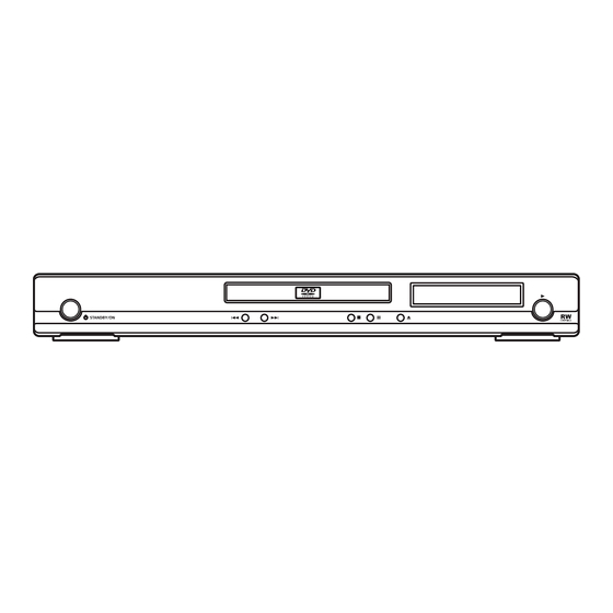
Page 92: Panel Facilities
8. PANEL FACILITIES DV-370-S... - Page 93 DV-370-S...
-
Page 94: Jigs List
7 Jigs list Name Jig No. Remarks Service Remote Control Unit GGF1381 diagnosis DVD Data Disc GGV1171 diagnosis (ID data setting) DVD Test Disc (DVD-Video) GGV1025 Check of DVD-Video CD Test Disc STD-905 Check of CD DV-370-S...
Need help?
Do you have a question about the DV-370-S and is the answer not in the manual?
Questions and answers