Daikin FFQ25B8V1B Installation Manual
Hide thumbs
Also See for FFQ25B8V1B:
- Service manual (501 pages) ,
- Service manual (398 pages) ,
- Service manual (403 pages)

Related Manuals for Daikin FFQ25B8V1B


Summary of Contents for Daikin FFQ25B8V1B
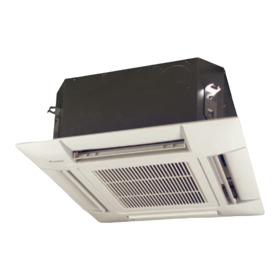
- Page 1 INSTALLATION MANUAL Split System air conditioners FFQ25B8V1B FFQ35B8V1B FFQ50B8V1B FFQ60B8V1B...
- Page 2 ≤45 ≤45 ≥1500* ≥1500* 585~660 ≥1500* ≥1500* 585~660* ≥1500* ≥1500* ≤20 ≤20 ≤300 1-1.5 m...
- Page 3 3PW25005-3C...
-
Page 4: Table Of Contents
Paper pattern for installation OTHER DAMAGE TO THE EQUIPMENT. BE SURE ONLY Srews (M5) for paper pattern for installation TO USE ACCESSORIES MADE BY DAIKIN WHICH ARE SPECIFICALLY DESIGNED FOR USE WITH THE Insulation for gas pipe fitting EQUIPMENT AND HAVE THEM INSTALLED BY A Insulation for liquid pipe fitting... -
Page 5: Selecting Installation Site
For the following items, take special care during Air flow directions construction and check after installation is finished Select the air flow directions best suited to the room and point of installation. (For air discharge in 2 or 3 directions, it is necessary to make field settings by means of the remote controller and to Tick close the air outlet(s). -
Page 6: Indoor Unit Installation
All the above parts are field supplied. NOTE Also, in cases where the temperature and humidity of the For other installation than standard installation, refrigerant piping sections might exceed 30°C or RH 80%, contact your Daikin dealer for details. reinforce refrigerant insulation (20 mm thicker). -
Page 7: Drain Piping Work
When connecting the flare nut, coat the flare both inside and • Make sure that heat insulation work is executed on the following 2 outside with ether oil or ester oil and initially tighten by hand 3 or spots to prevent any possible water leakage due to dew condensation. -
Page 8: Electric Wiring Work
Specifications for field wire When electric wiring work is not finished Remove the switch box lid and connect the power supply to Wire Length Size (mm the terminals. Between (1) (2) — H05VV-U4G figure indoor units Unit-Remote Vinyl cord with sheath Switch box lid 0.75~1.25 Max. -
Page 9: Wiring Example
PRECAUTIONS IRING EXAMPLE Observe the notes mentioned below when wiring to the power For the wiring of outdoor units, refer to the installation manual supply terminal board. attached to the outdoor units. Do not connect wires of different gauge to the same power Confirm the system type: supply terminal. -
Page 10: Field Setting
IELD SETTING NSTALLATION OF THE DECORATION PANEL Field setting must be made from the remote controller in accordance Read the chapter "Test operation" on page 7 before making a test run with the installation condition. without attaching the decoration panel. Setting can be made by changing the "Mode number", "FIRST Refer to the installation manual attached to the decoration panel. -
Page 11: Wiring Diagram
IRING DIAGRAM FIELD WIRING BLACK TERMINAL GREEN CONNECTOR PROTECTIVE EARTH (SCREW) WHITE YELLOW A1P....PRINTED CIRCUIT BOARD WIRED REMOTE CONTROLLER C1 ....CAPACITOR (FAN MOTOR) R1T ....THERMISTOR (AIR) F1U....FUSE (250 V/5 A) SS1 ....SELECTOR SWITCH (MAIN/SUB) HAP ....LIGHT EMITTING DIODE (SERVICE MONITOR - GREEN) RECEIVER/DISPLAY UNIT (ATTACHED TO WIRELESS REMOTE KPR .... - Page 12 NOTES NOTES...
- Page 13 1 2 3 1 2 3 1 2 3 1 2 3 1 2 3 1 2 3 1 2 3 1 2 3 1 2 3 1 2 3 1 2 3 1 2 3 1 2 3 1 2 3 1 2 3 1 2 3 1 2 3...
- Page 14 4PW23700-1B...
Need help?
Do you have a question about the FFQ25B8V1B and is the answer not in the manual?
Questions and answers