
Subscribe to Our Youtube Channel
Related Manuals for CP Plus CP-VK70S-VP


Summary of Contents for CP Plus CP-VK70S-VP
- Page 1 VIDEO ENTRY SYSTEM Power Supply Indoor Monitor Outdoor Station CP-VK70S-VP Operation Installation Manual...
-
Page 2: Outdoor Station
CP-VK70S-VP OUTDOOR STATION door lock indoor monitor Dimension: 58x135x39mm Water cover Protect the camera from outside water Provide lighting during night time for better LED assistant visibility Capture the image to sent to the monitor CCD camera Speaker Sound from the monitor is delivered... -
Page 3: Specification
Specification Power DC 14.5V Working electric current 200mA Camera lens 1/3 CCD 72 degree ken Illumination 0.05 LUX Communication duration 120s Communication method Duplex communication type Working temperature -20 +55°C IP rating Installation Process... -
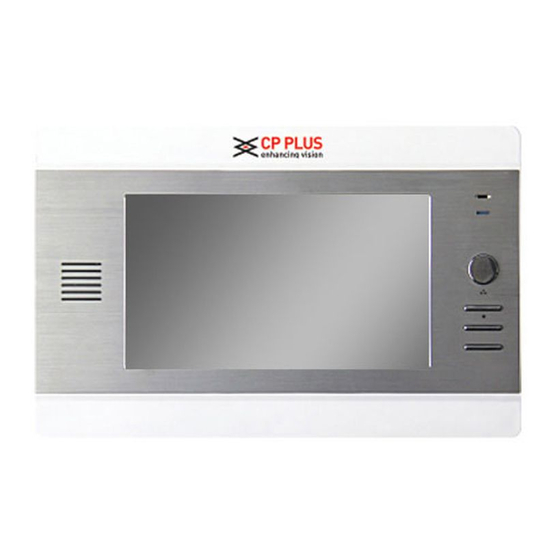
Page 4: Indoor Monitor
INDOOR MONITOR CP-VK 70-VP Dimension: 245x160x18mm NO. Icon Description NO. Icon Description TFT display Calling Door lock releasing Power indicator Microphone Chroma/contrast Speaker Brightness Talking Talking volume Monitor When connect more than one indoor monitor please short circuit J2 of the far the most monitor and open J2 of the other monitors. -
Page 5: Configuration Diagram
Sp ec i f i c at i o n Temperature: -10 ~ +55℃ Working condition RH≤95% Voltage DC14.5V ≤50mA Standby current ≤600mA Working current Mode Dual transmission Talking time 2 minutes Transmission distance≤28m, wire≥0.2mm Transmission distance≤50m, wire≥0.3mm Transmission distance≤70m, wire≥0.5mm Configuration Diagram Outdoor Outdoor... -
Page 6: Wiring Connections
Wiring Connections 1. Red 2. Blue 3. Yellow 4. White 1-Audio 2-GND 3-V+ 4-Video In d o o r Mo n i t o r... -
Page 7: Operation
Operation A view of the front door can be seen anytime the entrance button is pressed and a dialogue can be made with anyone at the front door. Press the button Ends the call... - Page 8 Indoor monitor call transferring Call from indoor monitor Other indoor monitors ring. Press the button, any After talking, press indoor monitor can talk button. with outdoor station. Press to end call.
-
Page 9: Installation Instruction
Installation instruction Notice 1. The installation place should b e farawa y fro m TV, video record player, PC etc. Electronic units with high intensity EMC. 2. Do not drop, knock or shake the unit. 3. Shut down the power for the unit while installing. 4. -
Page 10: Installing Diagram
Installing diagram Hole Back Plastic Bracket Screw Mounting bracket Hamulus INSTRUCTION: 1. Cables of LCC system: ① Non-wired cable. ② Diameter≥0.5mm , from outdoor station to the farthest monitor distance≤70m. 2. Each monitor should be parallel connected. monitor can be extended 3 monitors as maximum extension.
Need help?
Do you have a question about the CP-VK70S-VP and is the answer not in the manual?
Questions and answers