
Subscribe to Our Youtube Channel
Related Manuals for McIntosh MDA700


Summary of Contents for McIntosh MDA700
- Page 1 OWNER’S MANUAL MDA700 D/A Converter MDA700 McIntosh Laboratory, Inc. 2 Chambers Street Binghamton, New York 13903-2699 Phone: 607-723-3512 FAX: 607-724-0549...
-
Page 2: Customer Service
Six foot, shielded 2 conductor, with 1/8 inch stereo mini phone plugs on each end. 2. For additional connection information, refer to the owner’s manual(s) for any component(s) connected to the MDA700 D/A Converter. 3. Balanced and Unbalanced Outputs can be used separately or both simultaneously connected to different components. -
Page 3: Important Safety Instructions
Safety Instructions IMPORTANT SAFETY Attention: pour pevenir les chocs elecriques pas INSTRUCTIONS! utiliser cette fiche polarisee avec un prolongateur, une prise de courant ou un autre sortie de courant, sauf si les lames peuvent etre inserees afond ans en PLEASE READ THEM BEFORE laisser aucune partie a decouvert. - Page 4 Safety Instructions con’t, Introduction and Performance Features Introduction Care of Equipment: Performance Features · Balanced/Parallel D/A Design Repair of Equipment: · Automatic Sampling Frequency Selection · Four Selectable Digital Inputs · 20Bit Digital Filter · Balanced and Unbalanced Outputs · The Front Panel Display ·...
-
Page 5: Installation
Installation Installation 17-1/2" 444mm 7/32" 17-1/16" 5.3mm 433.4mm 1/4" Outline of Front Panel Edge of Cutout End Caps Panel Height 3-1/16" 3-9/16" 3 1/2" 77.8mm (Front View) 90.0mm 88.9mm 3/16" 5.1mm Support Shelf Bottom of Cutout and Top of Support Shelf Must Coincide Mounting Surface Mounting Bracket at Both Sides of the Rear Panel. -
Page 6: Balanced Audio
MDA700 Rear Panel Connections MDA700 Rear Panel Connections DATA IN receives operating data BALANCED AUDIO from a McIntosh Control Center OUTputs contain analog or McIntosh CD Transport and stereo signals to connect DATA OUT sends operating data to Balanced inputs of... - Page 7 How to Connect the MDA700 How to Connect the MDA700 Note: A Digital source component can be connected to either a COAXIAL or an OPTICAL Input. Note: An optional connecting method is to use Balanced cables from the BALANCED AUDIO OUT jacks to the Balanced Inputs of a Control Center.
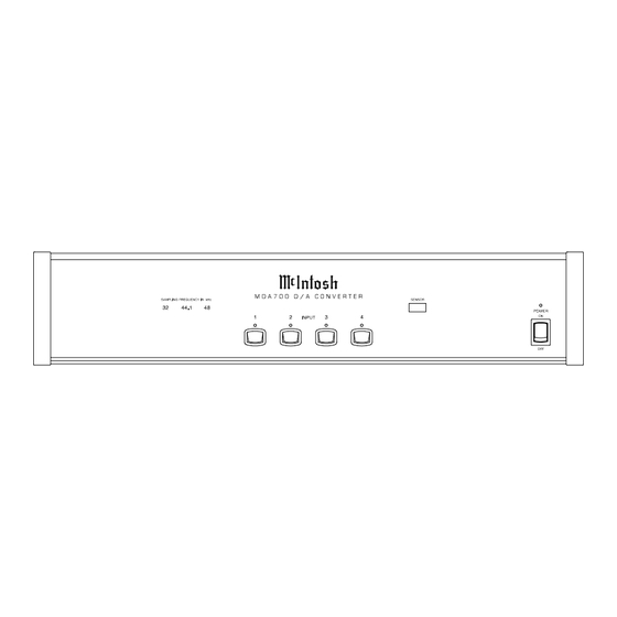
- Page 8 MDA700 Front Panel Display, Push- Buttons, and Switch MDA700 Front Panel Display, Push-Buttons, and Switch POWER ON Standby indicator Display indicates the SAMPLING IR SENSOR receivers FREQUENCY of the digital input commands from a re- signal mote control Selects Optical...
- Page 9 How to Operate the MDA700 How to Operate the MDA700 Power On Input Pushbuttons Selecting Inputs with Remote Controls Note: The Number pushbutton must be pressed within two seconds after the INPUT/AUTO SPACE/AM pushbutton is pressed. Reset of Microprocessors Frequency Display...
-
Page 10: Specifications
Specifications Specifications Frequency Response Power Requirements Total Harmonic Distortion NOTE: Refer to the rear panel of the MDA700 for the correct Signal To Noise Ratio voltage. Dimensions Dynamic Range Channel Separation Sampling Frequency D/A Conversion Digital Filter Analog Filter Maximum Voltage Output... - Page 11 Packing Instructions Packing Instructions...
Need help?
Do you have a question about the MDA700 and is the answer not in the manual?
Questions and answers