
Related Manuals for Fujitsu AU*A45LCLU


Summary of Contents for Fujitsu AU*A45LCLU
-
Page 1: Cassette Type
AIR CONDITIONER Cassette type DESIGN & TECHNICAL MANUAL SINGLE INDOOR AU A45LCLU AU A54LCLU OUTDOOR AO A45LBTL AO A45-54LCTL... -
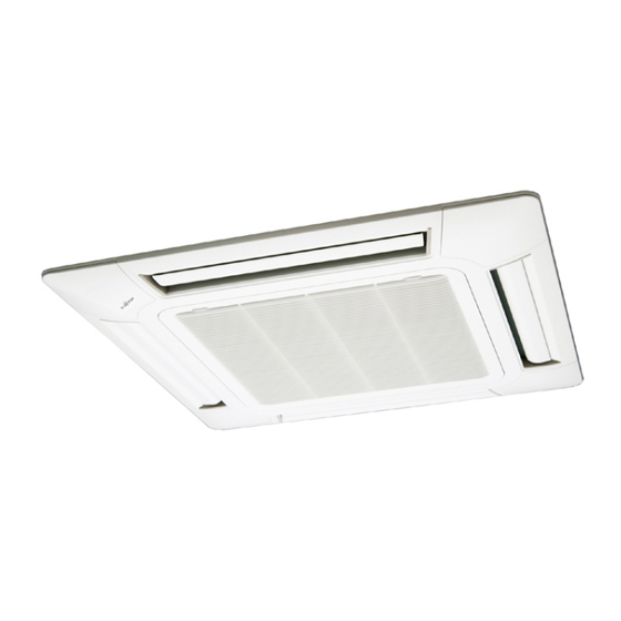
Page 2: Indoor Unit
1. INDOOR UNIT CASSETTE TYPE : AU A45LCLU AU A54LCLU D2D_AU041E/04 2011.03.01... -
Page 3: Table Of Contents
CONTENTS 1. INDOOR UNIT FEATURE ......................01 - 01 WIRED REMOTE CONTROLLER ........... 01 - 04 SPECIFICATIONS ..................01 - 06 DIMENSIONS ....................01 - 08 WIRING DIAGRAMS .................. 01 - 10 CAPACITY TABLE ..................01 - 11 6-1. COOLING CAPACITY .................01 - 11 6-2. -
Page 4: Feature
FEATURE MODELS „ „ AUA45LCLU / AOA45LBTL, AOA45LCTL AUA54LCLU / AOA54LCTL FEATURES „ „ AO A45LBTL AO A45LCTL Energy saving „ AO A54LCTL • All DC design • Heat exchange efficiency increased and larger air flow by adoption of new type turbo fan Advancement in comfort „... - Page 5 Wide & powerful airflow The wind is widely delivered by a high efficiency fan and round flap. Side view Airflow range of 2m / s Improvement of installation & maintenance „ • Adjustment of nut is possible after installation Mounting position of body can be fine adjusted after Decoration panel mounting.
- Page 6 FUNCTION SETTING „ „ Other functions „ • Performs operation matched to the number of outlets when 4 directions are unnecessary and outlets are blocked when the ceiling cassette is installed in a corner, etc. 4-way direction 3-way direction 4-way direction mode: Set when there are 4 outlets (shipped state).
-
Page 7: Wired Remote Controller
WIRED REMOTE CONTROLLER FEATURES „ „ Various timer setup (ON / OFF / WEEKLY) are possible. „ Equipped with weekly timer as standard function. „ (2 times Start / Stop per day for a week) When setting up a timer, operation mode and a temperature ... -
Page 8: Display Panel
FUNCTIONS „ „ START/STOP button Pressed to start and stop operation. SET TEMP. button Selects the setting temperature. MODE button Selects the operating mode (AUTO, HEAT, FAN, COOL, DRY). FAN button Selects the fan speed (AUTO, QUIET, LOW, MED, HIGH). ECONOMY (THERMO SENSOR) button Turns the economy efficient mode on and off. -
Page 9: Specifications
SPECIFICATIONS CASSETTE MODEL Type INVERTER HEATPUMP Indoor unit AUA45LCLU Model name Outdoor unit AOA45LBTL Power source 230V ~ 50Hz Available voltage range 198-264V ~ 50Hz Cooling European energy label Heating 12.5 Rated BTU/h 42700 Cooling 4.0-14.0 Min-Max BTU/h 13700-47800 Capacity 14.0 Rated BTU/h... - Page 10 CASSETTE MODEL Type INVERTER HEATPUMP Indoor unit AUA45LCLU AUA54LCLU Model name Outdoor unit AOA45LCTL A54LCTL Power source 230V ~ 50Hz Available voltage range 198-264V ~ 50Hz Cooling European energy label Heating 12.5 13.3 Rated BTU/h 42700 45400 Cooling 4.0-14.0 4.5-14.5 Min-Max BTU/h...
-
Page 11: Dimensions
DIMENSIONS MODEL : AUA45LC, AUA54LC „ „ Ceiling opening and hanging bolt pitch „ (Unit : mm) 950 (Panel frame) 860 - 910 (Ceiling opening) 840 (Body frame) 795 (Hanging bolt pitch) Refrigerant piping and drain piping positions „ Drain pipe (Connect the attached drain hose) Airflow split-flow duct and fresh air inlet positions „... - Page 12 INSTALLATION PLACE „ „ (Unit : mm) Strong and durable ceiling 1,500 3,000 or more or more Ceiling mode “Low” : 2.7 m Ceiling mode “Standard” : 3.2 m Obstruction Ceiling mode “High” : 4.2 m Floor 3-way directions setting „...
-
Page 13: Wiring Diagrams
WIRING DIAGRAMS MODEL : AUA45LC, AUA54LC „ „ - (01 - 10) -... -
Page 14: Capacity Table
CAPACITY TABLE 6-1. COOLING CAPACITY This table is created using the maximum capacity. MODEL : AUA45LC / AOA45LB „ „ 31.7 Indoor temperature °CDB °CWB °CDB 11.00 8.83 1.99 12.26 8.88 2.03 12.68 9.65 2.04 13.51 9.68 2.06 13.93 10.46 2.07 14.76 10.42 2.09 15.60 11.10 2.11 10.95 8.78... - Page 15 This table is created using the maximum capacity. MODEL : AUA54LC „ „ 33.3 Indoor temperature °CDB °CWB °CDB 11.73 9.03 2.69 13.07 9.08 2.73 13.52 9.87 2.75 14.41 9.90 2.78 14.85 10.69 2.79 15.74 10.65 2.82 16.64 11.35 2.85 11.72 9.04 2.59 13.06...
-
Page 16: Heating Capacity
6-2. HEATING CAPACITY This table is created using the maximum capacity. MODEL : AUA45LC / AOA45LB „ „ 31.7 Indoor temperature °CDB °CDB °CWB 11.43 4.49 11.16 4.58 10.89 4.67 10.62 4.77 10.35 4.86 12.38 4.49 12.08 4.58 11.79 4.67 11.49 4.77 11.20... - Page 17 This table is created using the maximum capacity. MODEL : AUA54LC „ „ 33.3 Indoor temperature °CDB °CDB °CWB 11.00 4.16 10.73 4.24 10.47 4.33 10.21 4.42 9.95 4.50 12.08 4.31 11.79 4.40 11.50 4.49 11.22 4.58 10.93 4.67 13.30 4.49 12.99 4.59...
-
Page 18: Fan Performance
FAN PERFORMANCE 7-1. AIR VELOCITY DISTRIBUTION Note: Condition 7-1-1. STANDARD MODE Fan speed : High Operation mode : FAN MODEL : AUA45LC Ceiling mode : Standard „ „ 4-way air outlet „ Unit : m/s 0.25 TOP VIEW 0.25 VERTICAL LOUVER : Upward Unit : m/s SIDE VIEW... - Page 19 Note: Condition Fan speed : High Operation mode : FAN Ceiling mode : Standard 3-way air outlet „ Unit : m/s 0.25 0.25 0.25 TOP VIEW VERTICAL LOUVER : Upward Unit : m/s SIDE VIEW 0.25 0.25 VERTICAL LOUVER : Upward Unit : m/s SIDE VIEW 0.25...
- Page 20 Note: Condition Fan speed : High Operation mode : FAN MODEL : AUA54LC Ceiling mode : Standard „ „ 4-way air outlet „ Unit : m/s TOP VIEW VERTICAL FLAP : Upward Unit : m/s SIDE VIEW VERTICAL FLAP : Upward Unit : m/s SIDE VIEW VERTICAL FLAP...
- Page 21 Note: Condition Fan speed : High Operation mode : FAN Ceiling mode : Standard 3-way air outlet „ Unit : m/s TOP VIEW VERTICAL FLAP : Upward Unit : m/s SIDE VIEW VERTICAL FLAP : Upward Unit : m/s SIDE VIEW VERTICAL FLAP : Downward - (01 - 18) -...
-
Page 22: Special Upward Mode
Note: Condition 7-1-2. SPECIAL UPWARD MODE Fan speed : High Operation mode : FAN MODEL : AUA45LC Ceiling mode : Standard „ „ 4-way air outlet „ Unit : m/s SIDE VIEW VERTICAL LOUVER 0.25 : Special upward MODEL : AUA54LC „... -
Page 23: Air Flow
7-2. AIR FLOW 7-2-1. 4-WAY OUTLET MODEL : AUA45LC „ „ Cooling / Heating „ Number of Fan speed rotations Air flow (r.p.m.) 1900 HIGH 1118 1640 1460 1250 QUIET MODEL : AUA54LC „ „ Cooling / Heating „ Number of Fan speed rotations Air flow... -
Page 24: 3-Way Outlet
7-2-2. 3-WAY OUTLET MODEL : AUA45LC „ „ Cooling / Heating „ Number of Fan speed rotations Air flow (r.p.m.) 1690 HIGH 1490 1340 1140 QUIET MODEL : AUA54LC „ „ Cooling / Heating „ Number of Fan speed rotations Air flow (r.p.m.) 1740... -
Page 25: Fresh Air
7-3. FRESH AIR MODEL : AUA45LC, AUA54LC „ „ Duct (Inside Dia. ø70mm) Duct Fan Static pressure required to take in fresh air Air flow (m /min) Installation „ 70 mm Refrigerant pipe Drain pipe 2.5 mm hole 62 mm 250 mm View(A) Fresh air inlet position(A) -
Page 26: Duct Connection
7-4. DUCT CONNECTION Outlet air „ AUA45LC Duct (Inside size. 350mm×100mm) Fan Speed High 1-way Fan Speed High 2-way Fan Speed Quiet 1-way L=10m Fan Speed L=5m Quiet 2-way L=1m Air flow (m /min) AUA54LC Fan Speed High 1-way Fan Speed High 2-way Fan Speed Quiet 1-way... - Page 27 PRECAUTIONS WHILE CONNECTING AIR OUTLET DUCT „ „ zConnect the air outlet duct at up to two locations among the four duct „ connection locations. (Do not connect ducts at three or more locations.) zBlow-off pattern when a branch duct is installed „...
-
Page 28: Noise Level Curve
OPERATION NOISE 8-1. NOISE LEVEL CURVE Condition Ceiling mode : Standard MODEL : AUA45LC „ „ Air outlet : 4-way air outlet Cooling Heating „ „ NC-65 NC-65 NC-60 NC-60 NC-55 NC-55 HIGH NC-50 NC-50 HIGH NC-45 NC-45 NC-40 NC-40 NC-35 NC-35 NC-30... -
Page 29: Sound Level Check Point
8-2. SOUND LEVEL CHECK POINT Microphone 1.5m Microphone CENTER - (01 - 26) -... -
Page 30: Electric Characteristics
ELECTRIC CHARACTERISTICS AU A45LC Model name AU A54LC Voltage 230 ~ Power supply Frequency Max. operating current (Indoor unit) Connection cable 1.5 - 2.5 Wiring spec. (Indoor unit to outdoor unit) Limited wiring length - (01 - 27) -... -
Page 31: Safety Devices
SAFETY DEVICES Model Protection form AU A45LC AU A54LC Circuit protection Current fuse (PCB) 3.15A 250V Thermal protection 110±15°C OFF Fan motor protection program 105±15°C ON - (01 - 28) -... -
Page 32: External Input & Output
EXTERNAL INPUT & OUTPUT Connector INPUT OUTPUT REMARKS Control input CN102 — (Operation/Stop) See external CN103 — Operation status output input/output settings for details. — Fresh air control output 11-1. EXTERNAL INPUT CONTROL INPUT (Operation/Stop) „ „ The air conditioner can be remotely operated by means of the following on-site work. Operation is started at the following contents by adding the contact input of a commercial ON/OFF switch to a connector on the external control PC board and turning it ON. -
Page 33: External Output
11-2. EXTERNAL OUTPUT OPERATION STATUS OUTPUT „ „ An air conditioner operation status signal can be output. Circuit diagram example „ Indoor Connected unit control PC board Connector Ex.)Relay unit Ex.)Display 24V DC Relay power supply *10 m Signal Field supply * Make the distance from the PC board to the connected unit within 10m. - Page 34 FRESH AIR CONTROL OUTPUT „ „ A signal linked to air conditioner indoor fan ON can be output. * However, signal becomes OFF during cold air prevention control operation. Circuit diagram example „ Indoor Connected unit control PC board Ex.) Fan Ex.) Relay unit 12 V Connector...
-
Page 35: Function Setting
FUNCTION SETTING 12-1. INDOOR UNIT INDOOR UNIT DIP SW Indoor unit address setting Remote controller signal code Jumper Wire Setting forbidden SWITCH POSITION „ „ MAIN PCB Indoor unit Printed circuit board DIP-SW SETTING „ „ Indoor unit address setting „... -
Page 36: Indoor Unit Setting
JUMPER WIRE SETTING „ „ Remote control unit signal code Indoor unit setting ( Factory setting) Jumper wire Remote control unit signal code JM 1 JM 2 Connect Connect Disconnect Connect Connect Disconnect Disconnect Disconnect - (01 - 33) -... -
Page 37: Indoor Unit (Setting By Remote Controller)
12-2. INDOOR UNIT (Setting by remote controller) • The function settings of the control of the indoor unit can be changed by this procedure according to the installation conditions. Incorrect settings can cause the indoor unit malfunction. • After the power is turned on, perform the “FUNCTION SETTING” according to the installation conditions using the remote controller. - Page 38 (5) Press the TIMER SET button to confirm the setting. Press the TIMER SET button for a few seconds until the setting value stops flashing. If the setting value display changes or if “- -” is displayed when the flashing stops, the setting value has not been set correctly. (An invalid setting value may have been selected for the indoor unit.) SU MO TU WE TH FR SA Setting value...
- Page 39 CONTENTS OF FUNCTION SETTING „ „ • Follow the instructions in the Local Setup Procedure, which is supplied with the remote control, in accordance with the installed condition. After the power is turned on, perform the Function Setting on the remote control. •...
- Page 40 1-4. Setting the vertical wind direction adjustment range •The use of “upward” is recommended if you wish to prevent draft. (The unit is factory-set to “00”) •Note that the ceiling may become dirty depending on your usage condition.When this happens, we recommend the use of the optional “PANEL SPACER KIT”.
-
Page 41: Wired Remote Controller
12-3. WIRED REMOTE CONTROLLER Can not be used. (Do not change) Dual remote controller setting Can not be used. (Do not change) DIP SW Can not be used. (Do not change) Can not be used. (Do not change) Memory backup setting SWITCH POSITION „... -
Page 42: Optional Parts
OPTIONAL PARTS Exterior Parts name Model No. Summary Air outlet shutter plate is Air outlet installed at the air outlet UTR-YDZC shutter plate when 3-way direction is performed. Wide panel hides the gap Wide panel UTG-AGYA-W between the ceiling hole and the Decoration panel. - Page 43 Exterior Parts name Model No. Summary It can be taken in fresh air of up to 10% of “high” air volume Fresh air intake UTZ-VXGA of the indoor unit by attaching Fresh Air Intake Kit to cassette type indoor unit. - (01 - 40) -...
- Page 44 2. OUTDOOR UNIT SINGLE TYPE : AO A45LBTL D2D_AO052E/01 2009.04.30...
- Page 45 CONTENTS 2. OUTDOOR UNIT 2-1. SPECIFICATIONS ..................02-01 2-2. DIMENSIONS ..................... 02-02 2-3. REFRIGERANT CIRCUIT ................. 02-03 2-4. WIRING DIAGRAMS ..................02-04 2-5. CAPACITY COMPENSATION RATE FOR PIPE LENGTH AND HEIGHT DIFFERENCE ..............02-05 2-6. ADDITIONAL CHARGE CALCULATION ........02-06 2-7.
-
Page 46: Specifications
2-1. SPECIFICATIONS Type INVERTER HEATPUMP Model name AO A45LBTL Power source 230V ~ 50Hz Available voltage range 198-264V ~ 50Hz Starting current 15.0 Cooling 6600 Airflow rate Heating 6600 Type × Q'ty Propeller × 2 Motor output 103 × 2 Cooling Sound pressure level dB(A) -
Page 47: Dimensions
2-2. DIMENSIONS MODEL : AOA45L „ „ (Unit : mm) Top view Front view Side view Air flow Drain cap 4-Ø12mm hole mounting places Bottom view MOUNTING POSITION „ „ When there are obstacles When there are obstacles When there are obstacles When there are obstacles at the at the back or front side. -
Page 48: Refrigerant Circuit
2-3. REFRIGERANT CIRCUIT MODEL : AOA45L „ „ - (02 - 03) -... -
Page 49: Wiring Diagrams
2-4. WIRING DIAGRAMS MODEL : AOA45L „ „ - (02 - 04) -... -
Page 50: Capacity Compensation Rate For Pipe Length
2-5. CAPACITY COMPENSATION RATE FOR PIPE LENGTH AND HEIGHT DIFFERENCE This table is created using the maximum capacity. MODEL : AOA45L „ „ Pipe length (m) COOLING – – – – 0.893 0.890 0.870 – – – 0.919 0.908 0.905 0.885 ... -
Page 51: Additional Charge Calculation
2-6. ADDITIONAL CHARGE CALCULATION MODEL : AO „ „ A45L Refrigerant type R410A Refrigerant amount 3350 Refrigerant charge „ Pipe length ~ 20 50g/m Additional charge 0 (Chargeless) +500 +1000 +1500 - (02 - 06) -... -
Page 52: Air Flow
2-7. AIR FLOW MODEL : AOA45L „ „ Cooling „ Number of rotations Air flow (r.p.m) 6600 Upper fan 1833 Lower fan 3884 Heating „ Number of rotations Air flow (r.p.m) 6600 Upper fan 1833 Lower fan 3884 - (02 - 07) -... -
Page 53: Operation Noise
2-8. OPERATION NOISE 2-8-1. NOISE LEVEL CURVE MODEL : AOA45L „ „ Cooling „ NC-65 NC-60 NC-55 NC-50 NC-45 NC-40 NC-35 NC-30 NC-25 NC-20 NC-15 1,000 2,000 4,000 8,000 Octave band center frequency,Hz Heating „ NC-65 NC-60 NC-55 NC-50 NC-45 NC-40 NC-35 NC-30... -
Page 54: 2-8-2. Sound Level Check Point
2-8-2. SOUND LEVEL CHECK POINT Air Fiow Microphone Microphone - (02 - 09) -... -
Page 55: Electric Characteristics
2-9. ELECTRIC CHARACTERISTICS Model Name AO A45L Voltage 230 ~ Power Supply Frequency Max. Operating Current 20.0 Starting Current 15.0 Main Fuse (Circuit breaker) Current *1) Wiring Spec. Power Cable 5.3 - 6.0 *2)Limited wiring length *1) Wiring Spec. : Selected Sample (Selected based on Japan Electrotechnical Standard and Codes Committee E0005) *2) Limited Wiring length :... -
Page 56: Safety Devices
2-10. SAFETY DEVICES Model Protection form AO A45L Current fuse (NEAR THE TERMINAL) 25A 250V Current fuse (NEAR THE TERMINAL) 10A 250V Circuit protection Current fuse (MAIN PRINTED CIRCUIT BOARD) 5A 250V Current fuse (MAIN PRINTED CIRCUIT BOARD) 3.15A 250V OFF : 130±20°C Fan motor protection Thermal protection program... - Page 57 2. OUTDOOR UNIT SINGLE TYPE : AOA45LCTL AOA54LCTL DTR_AO081E_01 2011.03.01...
- Page 58 CONTENTS 2. OUTDOOR UNIT SPECIFICATIONS ······························································································ 02 - 01 2. DIMENSIONS ········································································································ 02 - 02 INSTALLATION PLACE ················································································ 02 - 03 3-1. SINGLE OUTDOOR UNIT INSTALLATION ················································· 02 - 03 3-2. MULTIPLE OUTDOOR UNIT INSTALLATION ············································ 02 - 04 3-3. OUTDOOR UNIT INSTALLATION IN MULTI ROW ···································...
-
Page 59: Specifications
SPECIFICATIONS Model name AOA45LCTL AOA54LCTL Power source 1Ø 230V~ 50Hz Available voltage range 198-264V~ 50Hz Starting current 18.9 20.9 Cooling 6,750 6,750 Airflow rate Heating 6,200 6,850 Type × Q'ty Propeller × 2 Motor output Cooling Sound pressure level dB(A) Heating Dimensions (H ×... -
Page 60: Dimensions
DIMENSIONS MODEL : AOA45LC, AOA54LC „ „ (Unit : mm) Top view Terminal blocks 3-way valve ( Liquid ) 3-way valve ( Gas ) Ø28 (Cable port) Ø28 (Cable port) Pipe port Pipe port Pipe port Front view Side view Rear view Detail A Pipe &... -
Page 61: Installation Place
INSTALLATION PLACE 3-1. SINGLE OUTDOOR UNIT INSTALLATION WHEN THE UPWARD AREA IS OPEN „ „ (Unit : mm) Obstacles at front and Obstacles at rear Obstacles at rear and Obstacles at front only sides only only rear only 1000 or more 1000 or more WHEN AN OBSTRUCTION IS PRESENT ALSO IN THE UPWARD AREA „... -
Page 62: Multiple Outdoor Unit Installation
3-2. MULTIPLE OUTDOOR UNIT INSTALLATION WHEN THE UPWARD AREA IS OPEN „ „ (Unit : mm) Obstacles at rear only Obstacles at front only Obstacles at front and rear only 1500 or more 1500 or more WHEN AN OBSTRUCTION IS PRESENT ALSO IN THE UPWARD AREA „... -
Page 63: Refrigerant Circuit
REFRIGERANT CIRCUIT MODEL : AOA45LC, AOA54LC „ „ - (02 - 05) -... -
Page 64: Wiring Diagrams
WIRING DIAGRAMS MODEL : AOA45LC, AOA54LC „ „ - (02 - 06) -... -
Page 65: Capacity Compensation Rate For Pipe Length And Height Difference
CAPACITY COMPENSATION RATE FOR PIPE LENGTH AND HEIGHT DIFFERENCE MODEL : AOA45LC „ „ Pipe length (m) COOLING 0.879 0.846 0.814 Û 1 0.926 0.893 0.861 0.828 Indoor unit is 0.975 0.942 0.908 0.875 0.841 upper than 0.988 0.979 0.946 0.912 0.878 0.845... - Page 66 MODEL : AOA54LC „ „ Pipe length (m) COOLING 0.871 0.837 0.803 Û 1 0.921 0.886 0.851 0.816 Indoor unit is 0.971 0.936 0.900 0.865 0.830 upper than 0.988 0.975 0.940 0.904 0.868 0.833 outdoor unit. 0.992 0.992 0.979 0.943 0.908 0.872 0.836...
-
Page 67: Additional Charge Calculation
ADDITIONAL CHARGE CALCULATION MODEL : AOA45LC, AOA54LC „ „ Refrigerant type R410A Refrigerant amount 3,350 REFRIGERANT CHARGE „ Total pipe length 20 or less 50 (MAX) 40g/m Additional charge 1200 - (02 - 09) -... -
Page 68: Air Flow
AIR FLOW MODEL : AOA45LC, AOA54LC „ „ Cooling „ Number of MODEL rotations Air flow (r.p.m.) 6750 Upper fan AO A45LC 1875 Lower fan 3974 6750 Upper fan AO A54LC 1875 Lower fan 3974 Heating „ Number of MODEL rotations Air flow... -
Page 69: Operation Noise
OPERATION NOISE 9-1. NOISE LEVEL CURVE MODEL : AOA45LC „ „ Cooling Heating „ „ NC-65 NC-65 NC-60 NC-60 NC-55 NC-55 NC-50 NC-50 NC-45 NC-45 NC-40 NC-40 NC-35 NC-35 NC-30 NC-30 NC-25 NC-25 NC-20 NC-20 NC-15 NC-15 1,000 2,000 4,000 8,000 1,000 2,000... -
Page 70: Sound Level Check Point
9-2. SOUND LEVEL CHECK POINT Air Flow Microphone Microphone - (02 - 12) -... -
Page 71: Electric Characteristics
ELECTRIC CHARACTERISTICS Model name AO A45LC AO A54LC Voltage 230 ~ Power supply Frequency *1) Max. operating current 22.5 23.5 Main fuse (Circuit breaker) *2) Wiring spec. Current Power cable *1) The maximum current is the total current of indoor unit and outdoor unit. *2) Wiring spec. -
Page 72: Safety Devices
SAFETY DEVICES Model Protection form AO A45LC AO A54LC Current fuse 10A 250V, 3.15A 250V (Filter printed circuit board) Circuit protection Current fuse 3.15A 250V (Main printed circuit board) OFF : 150±15°C Fan motor protector Thermal protector ON : 120±15°C Thermal protection program OFF : 108°C (Compressor temp.) -
Page 73: External Input & Output
EXTERNAL INPUT & OUTPUT Input Output Connector Remarks Low noise mode ― CN10 Peak cut mode ― CN11 See external input/output settings ― Error status CN12 for details. ― Compressor status CN13 12-1. EXTERNAL INPUT ON/OFF of the "Low noise mode" and "Peak cut mode" functions can be specified by external signal. - Page 74 PEAK CUT MODE „ „ • Operation that suppressed the current value can be performed by means of the following on- site work. The air conditioner is set to the Peak cut mode when closing the contact input of a commercial ON/OFF switch to a connector on the outdoor control PC board.
-
Page 75: External Output
12-2. EXTERNAL OUTPUT ERROR STATUS OUTPUT „ „ • An air conditioner error status signal is produced when a malfunction occurs. Circuit diagram example „ Outdoor unit Connected unit control PC board Connector Power supply 1) Power supply ●Voltage (Chart sign=Vcc) : DC 24V or less 2) Load Load ●... - Page 76 COMPRESSOR STATUS OUTPUT „ „ • Compressor operation status signal is produced when the compressor is running. Circuit diagram example „ Outdoor unit Connected unit control PC board Connector Power supply 1) Power supply ●Voltage (Chart sign=Vcc) : DC 24V or less 2) Load Load ●...
-
Page 77: Function Setting
FUNCTION SETTING Caution Discharge the static electricity from your body before setting up the push buttons. Never touch the terminals or the patterns on the parts that are mounted on the board. 13-1. FIELD SETTING SWITCHES The positions of the switches on the outdoor unit control board are shown in the figure below. LED lamps Push buttons... -
Page 78: Setting Method
13-2. SETTING METHOD Stop the operation of air conditioner before this setting. 13-2-1. LOW NOISE MODE LED lamp part (1) Switch to “Local setting mode” by pressing [MODE] button (SW1) for 3 seconds or more. (2) Confirm (POWER / MODE) blinks 9 times, and press [ENTER] button (SW3). PUMP POWER LOW NOISE... -
Page 79: Peak Cut Mode
13-2-2. PEAK CUT MODE LED lamp part (1) Switch to “Local setting mode” by pressing [MODE] button (SW1) for 3 seconds or more. (2) Confirm (POWER / MODE) blinks 9 times, and press [ENTER] button (SW3). PUMP POWER LOW NOISE PEAK CUT DOWN ERROR... -
Page 80: Optional Parts
OPTIONAL PARTS Exterior Parts name Model No. Summary Use to operate the External input External connect UTY-XWZXZ3 and output function of Outdoor unit. - (02 - 22) -...
Need help?
Do you have a question about the AU*A45LCLU and is the answer not in the manual?
Questions and answers