Harman Kardon CDR2 Service Manual
Dual tray cd/cd-r/cd-rw recorder/player
Hide thumbs
Also See for CDR2:
- Technical manual (99 pages) ,
- Owner's manual (24 pages) ,
- Quick manual (4 pages)
Table of Contents
Advertisement
harman/kardon
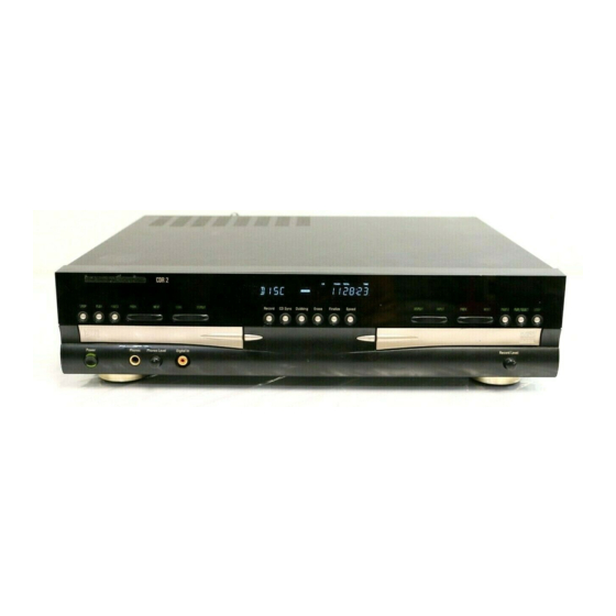
Dual Tray CD/CD-R/CD-RW Recorder/Player
Laser Beam Safety Precautions.........2
Safety Precautions............................... 3
Cdr2 Important Notes............................4
Specifications ..........................................6
Front Panel Controls................... .....7
Rear Panel Connections .. ................ 11
Remote Control Functions...............12
TROUBLESHOOTING GUIDE AND ERROR
MESSAGES........................................ ...... 14
Internal View ...........................................15
Disassembly Procedures .. ...............16
Ic Pinouts........ ....................................... 22
Detailed Troubleshooting Guide.......37
.
Model CDR2
SERVICE MANUAL
CONTENTS
250 Crossways Park Dr.
Woodbury, New York 11797
Bulletin 2000-08 Rev2................................. 66
Bulletin 2001-008....................................... 67
Tech Tip Hktt2001-02 Rev1.........................68
Tech Tip Hktt2003-04.................................69
Exploded View/Parts List ...................... 70
Cd-Record Mechanisms ..........................71
Block Diagrams........................................73
Pcb Layout ....................................................76
Electrical Parts List............................82
Schematic Diagrams ............................ 95
Wiring Diagram .....................................115
Package ...................................... .......... 116
Rev1 9/2005
Advertisement
Table of Contents
Troubleshooting

Related Manuals for Harman Kardon CDR2


Summary of Contents for Harman Kardon CDR2
- Page 1 SERVICE MANUAL CONTENTS LASER BEAM SAFETY PRECAUTIONS….…..2 BULLETIN 2000-08 Rev2....….….…..66 SAFETY PRECAUTIONS....….…….. 3 BULLETIN 2001-008....……..…….….. 67 CDR2 IMPORTANT NOTES....…..…….4 TECH TIP HKTT2001-02 Rev1..…..……..68 SPECIFICATIONS ......….……...6 TECH TIP HKTT2003-04……..…..……..69 FRONT PANEL CONTROLS………………..7 EXPLODED VIEW/PARTS LIST ..…..70 REAR PANEL CONNECTIONS .. …………..11 CD-RECORD MECHANISMS ..………..71...
-
Page 2: Laser Beam Safety Precautions
CDR2 harman/kardon LASER BEAM SAFETY PRECAUTIONS CLASS 1 LASER PRODUCT CAUTION Invisible laser radiation when the unit is open. Do not stare into beam. CAUTION: USE OF ANY CONTROLS, ADJUSTMENT, OR PROCEDURES OTHER THAN THOSE SPECIFIED HEREIN MAY RESULT IN HAZARDOUS RADIATION EXPOSURE. -
Page 3: Safety Precautions
CDR2 harman/kardon SAFETY PRECAUTIONS This symbol is intended to alert the user to the presence of uninsulated "dangerous voltage" within the product's enclosure that may be of sufficient magnitude to consti- tute a risk of electric shock to persons. This symbol is intended to alert the user to... -
Page 4: Cdr2 Important Notes
CDR2 harman/kardon CDR 2 Important Notes – including issues that may be confused with “defects” when they are part of normal operation 1. ALWAYS remove all discs before moving or repacking the unit! Since the discs are not seated on a spindle, they have a tendency to slip out of the trays. - Page 5 CDR2 harman/kardon analog mode to dub that particular disc. When recording in analog mode, make sure to use the level control to properly adjust the recording level. 14. In digital mode, if the CDR 2 senses a pause in the signal of more than 3 seconds, it will assume the recording session has ended and stop recording.
-
Page 6: Specifications
CDR2 harman/kardon SPECIFICATIONS Signal Format Playback Sampling Frequency 44.1 kHz D/A Conversion 96kHz, Multi-Bit Delta-Sigma Conversion Oversampling 128 Times Playback Specifications Frequency Response 2Hz – 20,050Hz Playback S/N 105dB Playback Dynamic Range 105dB Playback THD 0.005% / –88dB Analog Audio Output 2V RMS, ±... -
Page 7: Front Panel Controls
CDR2 harman/kardon Front-Panel Controls ¯ ¸ ˆ Ù Ú Ó ˘ ˜ Û Ò Ô & ı 1 Power Switch @ Finalize Ò Record-Deck Display Select 2 Status-Mode Indicator # Speed Ú Information Display 3 Play Deck $ Record-Deck Open Û... - Page 8 CDR2 harman/kardon Front-Panel Controls @ Finalize: Press this button when a record- Ô Record Deck Previous: This button has next track on a disc in play, or enter the track for programming or play when the disc is ing is complete to initiate the finalization two functions.
- Page 9 CDR2 harman/kardon Front-Panel Information Display A Random Indicators J Dual-Play Indicator S CD Indicators B Program Indicators K Information Displays T Record Indicator C Level Indicators L Time Indicators U Finalize Indicator D Repeat Indicators M Remaining-Time Indicators V Erase Indicator...
- Page 10 CDR2 harman/kardon L Time Indicator: This indicator lights in con- R Sample-Rate Converter: This indicator X Analog Indicator: This indicator lights junction with one of the time indicators OPQ lights when the Sample-Rate Converter is in use when an analog source is being recorded.
-
Page 11: Rear Panel Connections
‚ Remote IR Input: Connect the output of a processor or digital decoder. remote infrared sensor or the remote control output of another compatible Harman Kardon § Record (CDR)-Deck Coaxial-Digital product to this jack. This will enable the remote Input: This jack accepts the digital-audio input... -
Page 12: Remote Control Functions
CDR2 harman/kardon Remote Control Functions a Power-On Button b Play (CDP)-Deck Display Control c Play (CDP)-Deck Open d Play (CDP)-Deck Select e Program f Reverse Search g Single h Program Check i Previous-Track Skip j Play/Select k Random Play l Dub... - Page 13 CDR2 harman/kardon Remote Control Functions a Power-On Button: Press this button to l Dub: Press this button to begin a dub. See w CD Sync: Press this button once to begin turn the CDR 2 on. Note that in order for this page 20 for more information on dubbing.
-
Page 14: Troubleshooting Guide And Error Messages
• Replace the disc with a blank CD-R or CD-RW Audio disc NO AUDIO a non-audio disc is in the Record Drawer % • There is an internal problem with the CDR 2 • Contact an authorized Harman Kardon service depot SVC-1... -
Page 15: Internal View
CDR2 harman/kardon INTERNAL VIEW TOP VIEW – › POWER P.C. BOARD (PCB-1) CDR P.C. BOARD (PCB-4) — œ IO P.C. BOARD (PCB-2) FRONT P.C. BOARD (PCB-5) ˜ CDP MECHANISM ASSY (MECHA-1) HEADPHONE P.C. BOARD (PCB-6) ™ ž CDR MECHANISM ASSY (MECHA-2) REC VOLUME P.C. -
Page 16: Disassembly Procedures
CDR2 harman/kardon DISASSEMBLY PROCEDURES 1. PCB-(POWER SWITCH) REMOVAL <Fig 1> – — 1. Power on and press open buttons in Fig.1 ˜ ™ 2. Remove the CD Door by pulling it toward you gently. 2. CABINET TOP REMOVAL <Fig 2>... - Page 17 CDR2 harman/kardon 3. FRONT PANEL ASSEMBLY REMOVAL <Fig 3> – 1. Detach the connector in Fig.3 – œ 2. Remove the front panel by hook-off in Fig.3 and pulling it toward you gently. 3. Detach the connector 4. POWER LEVER ASSEMBLY REMOVAL <Fig 4>...
- Page 18 CDR2 harman/kardon 5. PCB-1(Power) REMOVAL <Fig 5> – ˜ 1. Detach the connector in Fig.5 ™ ➓ 2. Remove screws in Fig.5, and then remove PCB-1. 6. PCB-2(I/O) REMOVAL 7 15 14 13 10 9 <Fig 6> – ™ 1. Detach the connector in Fig.6...
- Page 19 CDR2 harman/kardon 7. MECHA-1 (CDP) ASSEMBLY REMOVAL <Fig 7> – ™ 1. Remove screws in Fig.7 š 2. Detach the connector in Fig.7, and the remove the Mecha-1. 8. MECHA-2 (CDR) ASSEMBLY REMOVAL <Fig 8> – ™ 1. Remove screws in Fig.8...
- Page 20 CDR2 harman/kardon 9. PCB-5 (Front) REMOVAL ™ – š — ˜ › œ <Fig 9> – ˜ 1. Remove screws in Fig.9 2. Pull-out the PCB-5 from the Front Panel. 10. PCB-6(Headphone) Removal. › œ 1. Remove screws in Fig.9 ›...
- Page 21 CDR2 harman/kardon 13. PCB-4(CDR) REMOVAL – ˜ 1. Pull-out the PCB-4 by hook-off in Fig.11 from the MECHA-2(CDR) ™ œ 2. Detach the connector in Fig.11 ™ 3. Remove the PCB-4 from the MECHA-1(CDR) š – — › œ <Fig 11>...
- Page 22 CDR2 harman/kardon BLOCK DIAGRAM 1. AK8563 ➀ Block Diagram...
- Page 23 CDR2 harman/kardon ➁ Pin Functions Pin Number Designator Functions AVDD3 Analog Positive Power Source Pin FPDIN Laser Monitor Diode Contact Pin FVREF Reference Voltage Level Input Pin for APC FPDO Laser Monitor Output (Connect I/V conversion resistor between FPDIN)/Laser Monitor Voltage Input...
- Page 24 CDR2 harman/kardon Pin Number Designator Functions AVSS2 Analog Ground Pin AVDD2 Analog Positive Power Source Pin XRST Register Reset Pin. "L" Register Initialization WLDON Write LD Control Input. "L" Write APC Setting to Zero, "H" LD 0N AGCON Wobble AGC Enable Input. "H" AGC ON, "L" AGC reset...
-
Page 25: Block Diagram
CDR2 harman/kardon 2. RL5E808 ➀ Block Diagram DEFS RD(15:0) DSFS Subcode ROEB Subcode if SUBIN RCAS0B Operator RCAS1B:RWE1B SUBCK RWE0B DRAM if RRAS0B RA11:RRAS1B RA10:RRAS2B LRCKIN RA9:RRAS3B SDIN RA(8:0) CD-DA if BTCK Buffer C2PO Manager DASPB CS3FXB CS1FXB CIRC RAM if... - Page 26 CDR2 harman/kardon 3. M56788 ➀ Block Diagram VBS1 VBS2 VBS2 IN3- IN3+ IN1+ VBS1 OUT3 IN1- OUT1 CH3IN VBS2 VBS1 VM1(+) VM3(+) Vrefm1 Vrefm2 VM3(-) VM1(-) VBS1 VBS2 VM2(+) VM4(+) VM2(-) VREFO VM4(-) Hi:Sleep OUT2 BIAS VBS2 IN4- VBS1 VBS1...
- Page 27 CDR2 harman/kardon 5. MN12511 ➀ Block Diagram D 1 5 ~ D 0 N S D I N S D O N S C K N C E...
- Page 28 CDR2 harman/kardon CXD3011R-1 Block Diagram...
- Page 29 CDR2 harman/kardon PIN FUNCTIONS...
- Page 30 CDR2 harman/kardon...
- Page 31 CDR2 harman/kardon...
- Page 32 CDR2 harman/kardon...
- Page 33 CDR2 harman/kardon AK4393 Block Diagram...
- Page 34 CDR2 harman/kardon AK5351 Block Diagram...
- Page 35 CDR2 harman/kardon ➁ Pin Descriptions Pin Name FUNCTION AINR+ Right channel analog positive input pin AINR- Right channel analog negative input Pin VREF Voltage Reference output pin (VA-2.6V) Normally connected to VA with a 0.luF ceramic capacitor in parallel with a 10uF electrolytic capacitor.
- Page 36 CDR2 harman/kardon Pin Name FUNCTION CMODE Master Clock Selection pin "L": MCLK=256fs "H": MCLK=384fs SMODE1 Serial Interface Mode Select pin SMODE2 Defines the directions of LRCK, SCLK and FSYNC pins and Output Data Format. SMODE2 is pull-down pin. SMODE1 SMODE2...
-
Page 37: Troubleshooting Guide
CDR2 harman/kardon TROUBLESHOOTING GUIDE 1. Initial Lead-in Operation 2. Trouble List(Circuit) (In the Initial Lead-in Operation Mode) A. Pick-Up doesn’t move to the inner-track. B. Pick-Up lens doesn’t move up and down. C. Disc doesn’t rotate. D. The Laser(RED) of Pick-Up doesn’t light. - Page 38 CDR2 harman/kardon...
- Page 39 CDR2 harman/kardon...
- Page 40 CDR2 harman/kardon...
- Page 41 CDR2 harman/kardon...
- Page 42 CDR2 harman/kardon Reset or Power Check...
- Page 43 CDR2 harman/kardon System Check...
- Page 44 CDR2 harman/kardon...
- Page 45 CDR2 harman/kardon...
- Page 46 CDR2 harman/kardon Tray Operation Abnormal...
- Page 47 CDR2 harman/kardon Sled Motor Operation Abnormal...
- Page 48 CDR2 harman/kardon Focus Actuator Operation Abnormal...
- Page 49 CDR2 harman/kardon Spindle Motor Operation Abnormal...
- Page 50 CDR2 harman/kardon RFDC Output Operation Abnormal...
- Page 51 CDR2 harman/kardon Focus Servo Unstable Tracking Servo Unstable...
- Page 52 CDR2 harman/kardon Spindle Control Abnormal1 Spindle Control Abnormal2...
- Page 53 CDR2 harman/kardon Disc Recognition Abnormal...
- Page 54 CDR2 harman/kardon Spindle Control Abnormal1 Spindle Control Abnormal2...
- Page 55 CDR2 harman/kardon Laser Operation Abnormal...
- Page 56 CDR2 harman/kardon LD Check (no reading)
- Page 57 CDR2 harman/kardon LD Check (no recording)
- Page 58 CDR2 harman/kardon...
- Page 59 CDR2 harman/kardon Write Failure...
- Page 60 CDR2 harman/kardon Writing Part Check...
- Page 61 CDR2 harman/kardon ALPC Logic Circuit Check...
- Page 62 CDR2 harman/kardon...
- Page 63 CDR2 harman/kardon...
- Page 64 CDR2 harman/kardon ASIC IC 301( 74 , 105 , 107 BITSTR~1. IC 301( 80 , 86 , 88...
- Page 65 CDR2 harman/kardon U-COM IC 202( 12 , 14 , 16 12 , 14...
- Page 66 Subject: Complaints Related To Early Software In the event you receive a CDR2 with one or more of the symptoms listed below, an upgrade in the software may be necessary. Confirmation may be made by checking the serial numbers listed below.
- Page 67 In the event you receive a CDR2 Player/Recorder with this complaint: “There is a mechanical clicking noise in the player section, either when the CDR2 turns “ON” or when it starts to play a CD”: 1) Clean and re-grease all the mechanical tracking parts:...
- Page 68 TIP# HKTT2001-02 Rev1 Issue: Power Failure During A Recording Session Power loss is defined as: CDR2 was switched OFF by the POWER button on the front panel, or by the OFF button on the remote control, or through a power failure.
- Page 69 5) Certain CDR disc brands may only copy at X1 speed. Try another brand. Otherwise replace IC209. CDR2 DEAD (NO POWER/SHUTDOWN) AFTER IT WAS MOVED, SHIPPED, OR DROPPED: Check for a broken Power Supply traces in PCB area around power transformer.
-
Page 70: Exploded View/Parts List
CDR2 harman/kardon EXPLODED VIEW/PARTS LIST MAIN SECTION REF.NO. PART NO DESCRIPTION 4940S-6939A KNOB POWER 3790S-M079A WINDOW POWER 3300S-X002A PLATE PET 6871RZ1963A PCB ASSY LED 4510S-1019A LEVER POWER 3580S-C108A DOOR PLAY 3580S-C105A DOOR ACDR 6721R-0301A MECHA Q1(PLAYER) 4405H-1068C MECHA E2 3610S-0192A... - Page 71 CDR2 harman/kardon CD PLAY SECTION REF.NO. PART NO DESCRIPTION 4930H-1061A HOLDER ASSY CLAMP(Q1, ACDR) 4861R-D004A CLAMP ASSY Q1 & E2 ACDR 4931R-0033A HOLDER ASSY CLAMP(Q1, ACDR) 3390H-1016C TRAY DISC, BLACK) 4400H-1009A BELT GM-RT 1332A 4560H-1005A PULLEY MOTER(GM-R512) 4470H-115A GEAR LOADING(Q1)
- Page 72 CDR2 harman/kardon CD RECORD SECTION REF.NO. PART NO DESCRIPTION 4861R-0005A CLAMP ASSY ACDR E2(4861H-0008A) 3390R-0007A TRAY DISC(E2, 3390H-1011C) 4400R-0007A BELT ACDR E2(4400H-1003A) 4560R-0009A PULLEY GEAR(E2, 4560H-1004A) 4681R-1022A MOTOR ASSY LOADING(E2, 4681H-1024A) 4470R-0059A GEAR LOADING(E2, 4470H-1015A) 4470R-0060A GEAR MIDDLE(E2, 4470H-1016A) 3040R-0030A...
-
Page 73: Block Diagrams
CDR2 harman/kardon BLOCK DIAGRAM CD RECORD SECTION... - Page 74 CDR2 harman/kardon CD PLAY SECTION...
- Page 75 CDR2 harman/kardon IO SECTION COAXIAL IN (1) 74HC04 74HC04 BUFFER BUFFER H/P OUT LRCK DATA BCLK BU4053 BU4053 AK4394 AK4394 ANALOG P OUTPUT (DAC) (DAC) POWER ANALOG R OUTPUT DOWN MUTE DEMPH 74HC04 RELAY ANALOG INPUT 74HC04 BU4053 BU4053 BUFFER...
-
Page 76: Pcb Layout
CDR2 harman/kardon PCB LAYOUT CD-PLAY TOP SECTION... - Page 77 CDR2 harman/kardon CD-PLAY BOTTOM SECTION...
- Page 78 CDR2 harman/kardon CD-RECORD TOP SECTION CD-RECORD BOTTOM SECTION...
- Page 79 CDR2 harman/kardon AUDIO TOP SECTION AUDIO BOTTOM SECTION...
- Page 80 CDR2 harman/kardon FRONT SECTION...
- Page 81 CDR2 harman/kardon POWER SECTION...
- Page 82 CDR2 harman/kardon Ref. No. Part No. Description CHASSIS MISCELLANEOUS 564-036D PLUG CONTACT CORD,PHONE 564-036J CORD DIGIATL 1.5M 1365#30 6852R-N001A CORD 1.5M NAMIL REMOTE CONTROL 255-717A HEAT SINK DIODE(GSA-PA10/FA-5000) PT901 6170S-I03AH TRANSFORMER,POWER 6850R-GZ20Y CABLE,FLAT ACDR I/O PART P.C. BOARD CAPACITORS C101,106,120,123,127...
- Page 83 CDR2 harman/kardon Ref. No. Part No. Description DIODE D201 0DD202009AG DAN202U-T107 ROHM-J FILTER(CIRC) L103,104 6200S-JC01A HB-1M2012-121JT CERATECH SMD T INTEGRATED CIRCUITS IC101 657-063A LTV-817B,PHOTO COUPLER(LITEON) IC102,103 0IJR456500A NJM4565M-A,OP-AMP,JRC IC104,404 0IJR553200A NJM5532 OP AMP IC105,401 0IAK439320A AK4393VF-E2 28SOP TP DAC 1K RE...
- Page 84 CDR2 harman/kardon Ref. No. Part No. Description R451 0RH1002D622 10K 1/10W 5 D.R/TP R476,477 0RH0222D622 22 1/10W 5 D.R/TP TRANSISTOR Q201,205,405 0TR103009AF KRA103M-TP (KRA2203) KEC Q202,203,206,401,402 0TR319809AC KTC3198-TP-BL (KTC1815)KEC Q204,207,208,403,404 0TR130209AA KTD1302 MUTING TP KEC TO92 Q410,411 0TR319809AC KTC3198-TP-BL (KTC1815)KEC POWER P.C.
- Page 85 CDR2 harman/kardon Ref. No. Part No. Description Q905 0TR103009AE KRC103M-TP (KRC1203) KEC Q906,907 0TR130209AA KTD1302 MUTING TP KEC TO92 FRONT P.C. BOARD CAPACITORS C801,802,809,810 0CN1040K948 0.1UF 50V Z F TA26 D C804 0CE1073F638 100M SRE 16V M FM5 TP(5) C805,806,807 0CN2230H948 0.022M 25V Z F TA26...
- Page 86 CDR2 harman/kardon Ref. No. Part No. Description CONNECTOR CN806 6631R-E006A IL-S/9073AN 6PIN 400M/M UL2547 J801 563-638E SPECIAL RING TER. AY 1007#24 G DIODE ZD801,802 0DZ510009EB MTZ5.1B 0.5W TP ROHM-K JACK JK802 572-359J SOQ4694-01-4101 K-HOSIDEN H=6. JK801 6612S-C004A WA6013-35-40 PARK ELEC ORANGE...
- Page 87 CDR2 harman/kardon Ref. No. Part No. Description C726,727,728,729 0CH4101K412 100P 50V J COG 1.6X0.8 R/TP COIL L301,401 6140H-B003G NLC322522T-100K 10MH L501 6140H-B003G NLC322522T-100K 10MH CONNECTOR PN201 6630R-FB02Q 04-6232-117-008-800 ELCO 17PIN PN301 6630R-FB02D 04-6232-104-008-800 ELCO 4PIN PN302 6630R-FB06F 04-6232-106-102-800 ELCO 6PIN...
- Page 88 CDR2 harman/kardon Ref. No. Part No. Description R220 0RH1504C622 1.50M 1/16W 5% D R/TP R221 0RH2203C622 220K 1/16W 5 D.R/TP R228,421,423,425,523 0RH1002C622 10K 1/16W 5 D.R/TP R230,231 0RH2200C622 220 1/16W 5 D.R/TP R232,233,406,407,565 0RH1500C622 150 1/16W 5 D.R/TP R234,417,524,541,542 0RH4700C622 470 1/16W 5 D.R/TP...
- Page 89 CDR2 harman/kardon Ref. No. Part No. Description C211 0CH1822K562 8200P 50V K X7R 1.6X0.8 R/TP C215,294,297,331,332 0CH1103K562 10000F 50V K X7R(X) 1508 R/TP C218,219,220,222,223 0CH1104H942 0.1000UF 25V Z Y5V(F) 1508 R/T C225,226,227,228,231 0CH1104H942 0.1000UF 25V Z Y5V(F) 1508 R/T C232,233,234,235,236 0CH1104H942 0.1000UF 25V Z Y5V(F) 1508 R/T...
- Page 90 CDR2 harman/kardon Ref. No. Part No. Description C639 0CH1681K562 680P 50V K X7R 1.6X0.8 R/TP C644 0CH4100K172 10P 50V D N750 1.6X0.8 R/TP C650 0CH7476C621 47UF 6.3V M 3528 TP(-) C663,695,865 0CH7106C611 10UF 6.3V M 3216 TP(-) C672,673,676,857,858 0CH7106C611 10UF 6.3V M 3216 TP(-)
- Page 91 CDR2 harman/kardon Ref. No. Part No. Description IC211,405 0INS740400Y 74VHC04MTCX 14TSSOP TP HEX INV IC212,555,761,854 0ITO453000C TC4W53FU SSOP 8PIN IC213 0INS704500C NC7SZ04M5X 5P SOT23-5 TP INVER IC214 0ITO704000A TC7S04F INVERTER(GE85L) IC301 0IXL103144A XCS10-3TQ144C 144QFP BK FPGA IC302 0IWI242573A W24257AS-35 (TAPE&REEL) 1K/TP...
- Page 92 CDR2 harman/kardon Ref. No. Part No. Description R223,224 0RH4700C622 470 1/16W 5 D.R/TP R227,228,230,231,232 0RH1000C622 100 1/16W 5 D.R/TP R233,236,237,241,242 0RH1000C622 100 1/16W 5 D.R/TP R239,240 0RH6800C622 680 1/16W 5 D.R/TP R244 0RH3001C622 3K 1/16W 5% D R/TP R249,250,251,504,528 0RH4703C622 470K 1/16W 5 D.R/TP...
- Page 93 CDR2 harman/kardon Ref. No. Part No. Description R553,554,555 0RH0101G622 1 OHM 1 / 4 W 3216 5% D R/TP R559,560,568,593,618 0RH0000C622 0 1/16W 5 D.R/TP R561,988 0RH1502C622 15K 1/16W 5 D.R/TP R562,861,863,981,983 0RH6802C622 68K 1/16W 5 D.R/TP R563 0RH2703C622 270K 1/16W 5 D.R/TP...
- Page 94 CDR2 harman/kardon Ref. No. Part No. Description R977 0RH4701C622 4.7K 1/16W 5 D.R/TP R984,986 0RH6802C622 68K 1/16W 5 D.R/TP R987,989,991,993 0RH0000C622 0 1/16W 5 D.R/TP R994 0RH1002C622 10K 1/16W 5 D.R/TP R997 0RH4702C622 47K 1/16W 5 D.R/TP RESONATOR X201 6212HA0202A CSACV20.00MXJ040-TC20 MURATA 2...
-
Page 95: Schematic Diagrams
SCHEMATIC DIAGRAMS CDR2 harman/kardon CD-RECORD SECTION-1... - Page 96 CDR2 harman/kardon CD-RECORD SECTION-2...
- Page 97 CDR2 harman/kardon CD-PLAY SECTION...
- Page 98 CDR2 harman/kardon AUDIO-SECTION...
- Page 99 FRONT SECTION CDR2 harman/kardon...
- Page 100 CDR2 harman/kardon POWER SECTION...
- Page 101 CD RECORD TILE 1...
- Page 102 CD RECORD - TILE 2...
- Page 103 CD RECORD - TILE 3...
- Page 104 CD RECORDII - TILE 1...
- Page 105 CD RECORDII - TILE 2...
- Page 106 CD RECORDII - TILE 3...
- Page 107 CD RECORDII - TILE 4...
- Page 108 CD PLAY - TILE 1...
- Page 109 CD PLAY - TILE 2...
- Page 110 CD PLAY - TILE 3...
- Page 111 CD PLAY - TILE 4...
- Page 112 AUDIO - TILE 1...
- Page 113 AUDIO - TILE 2...
- Page 114 AUDIO - TILE 3...
-
Page 115: Wiring Diagram
CDR2 WIRING DIAGRAM harman/kardon CDR2 harman/kardon... -
Page 116: Package
CDR2 harman/kardon PACKAGE Polyethylene Bag Owner’s Guide 3880R-0004A 3828SND043A Important Safeguards 3840R-G001A REMOTE CONTROL 6711R1Z017A or HG23G01 Soft Sheet 694-003Q Cushion 3920R-0087A Carton Box 3890S-C093A...