
Summary of Contents for DA Data Cool Series
- Page 1 Data Cool Installation, Operation and Maintenance Manual 2 and 3 ton Air, Water and Glycol Cooled DX and Chilled Water...
- Page 2 CONGRATULATIONS ON THE SELECTION OF A DATA AIRE PRECISION ENVIRONMENTAL CONTROL SYSTEM. PROPER INSTALLATION, OPERATION AND MAINTENANCE OF THIS EQUIPMENT WILL ENSURE YEARS OF OPTIMAL PERFORMANCE. This manual is intended to assist trained service personnel by providing necessary guidelines for this particular equipment. Installation and service to Data Aire units should be done by qualified individuals with an adequate background in areas such as HVAC, electrical, plumbing and electronics, as applicable.
-
Page 3: Table Of Contents
Table of Contents MODEL IDENTIFICATION ................ 5 INSTALLATION ..................Room Considerations ....................6 Inspection ........................6 Locating the Unit ......................6 1.3.1 Indoor Condensing Unit ....................7 Leveling Legs ......................7 Paperwork ......................... 7 Storage ........................7 PIPING ......................Split Air Cooled Unit Piping ..................8 2.1.1 Liquid Lines ....................... - Page 4 Table of Contents, continued CHARGING ........................15 5.1 Voltage Phase Check ......................15 5.1.1 Evaporator ........................15 5.1.2 Secondary Heat Exchanger .................... 15 Air Cooled Systems ....................... 15 5.2.1 Split Indoor Air Cooled Systems Charging ..............15 5.2.2 Fan Speed Control System Charging ................16 Water/Glycol Cooled Systems ..................
-
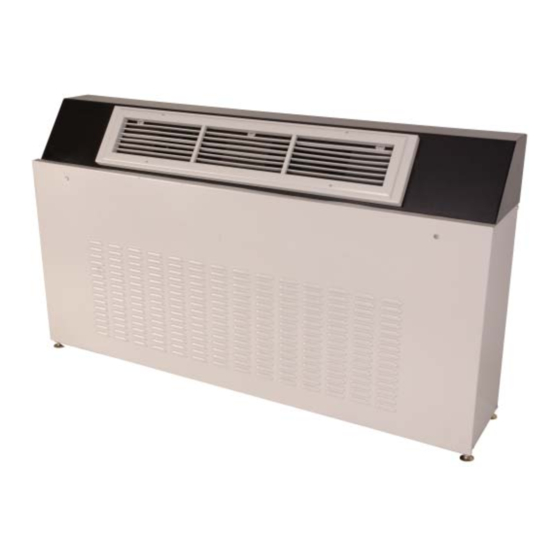
Page 5: Model Identification
Model Identification... -
Page 6: Installation
1.0 INSTALLATION There is no intent on the part of Data Aire, Inc. to define local codes or statutes which may supercede common trade practices. The manufacturer assumes no responsibility for their interpretation. Consult local building codes and the National Electrical Code for special installation requirements. -
Page 7: Indoor Condensing Unit
Note to Installing Contractor: Condensation formation and frequent humidifier flushing (when humidifier is installed) are normal functions of this equipment. Drain connections must be made to ensure proper water removal. Unit will require drain connections for condensate removal and water connections possibly for humidifier (when installed) makeup water, chilled water and/or hot water. -
Page 8: Piping
2.0 PIPING Split Air Cooled Unit Piping Refer to the attached Line Sizing chart on page 24 for a guideline for sizing refrigerant lines. The ultimate responsibility for line size selection is that of the installing contractor or project engineer. Data Aire does not assume this responsibility. -
Page 9: Connection Sizes, Air Cooled Units
2.1.3 Connection Sizes, Air Cooled Units Model Liquid Suction DACU 02 1/2" 3/4" Note: Unit will have a Liquid Line and DACU 03 1/2" 3/4" Suction Line DACU 04 1/2" 3/4" DACU 05 1/2" 3/4" Field connections at the indoor evaporator and remote condensing unit will not necessarily be the same as the field pipe size required. -
Page 10: Water/Glycol Cooled Unit Piping
Water/Glycol Cooled Unit Piping The required field installed condenser water pipe sizes may or may not be the same as the connection sizes at the evaporator or fluid cooler. This will depend on the length of pipe and the calculated pressure drop of peripheral components. -
Page 11: Connection Sizes, Water/Glycol Cooled Units
2.2.3 Connection Sizes, Water/Glycol Cooled Units Evaporator Water IN and OUT Model Connections, OD DACW/G 02 3/4” DACW/G 03 3/4” 2.2.4 Connection Sizes, Fluid Coolers Fluid Cooler Water IN and OUT Model Connections, OD DAFC 06 1-5/8" DAFC 07 1-5/8" DAFC 09 1-5/8"... -
Page 12: Humidifier Piping
Humidifier Piping The optional humidifier offered on Data Cool is a steam generator type with a disposable cylinder. The humidifier makeup water should be brought to the humidifier through the field connection opening using 1/4" copper tubing. A compression fitting is provided at the humidifier. A shutoff valve should be provided outside the air conditioner to allow disconnection for service. -
Page 13: Electrical Connections
3.0 ELECTRICAL CONNECTIONS Before proceeding with the electrical connections, make certain that the volts, hertz and phase correspond to that specified on the unit electrical nameplate. Units damaged from incorrect power input will not be covered under warranty. Use copper conductors only. Electrical Service Check to be sure the service provided by the utility is sufficient to handle the additional load imposed by this equipment. -
Page 14: Installation Of Remote Outdoor Heat Exchanger
4.0 INSTALLATION OF REMOTE OUTDOOR HEAT EXCHANGER Rigging This section covers outdoor condensing units and fluid coolers. Outdoor heat exchangers should be moved to their (typically rooftop) mounting location using a crane or fork lift. Each fan section has supports with lifting holes at the top. Do not lift with a choke sling around the unit. -
Page 15: Electrical Service
Electrical Service Refer to Sections 3.1 to 3.5 for information regarding line voltage and control voltage wiring details. Air Cooled Condensing Unit - Model DRCU 4.4.1 Fan Speed Control Standard outdoor air cooled condensing units have a fan speed controller on the first fan. On single-fan condensing unit this is the only means of control. -
Page 16: Fan Speed Control System Charging
Start the evaporator fan and compressor. Check the liquid line sight glass to get a feel for the approximate charge. Bubbles in the sight glass are not unusual at this point and can be caused by flashing from liquid line pressure drop, low sub-cooling or low charge. It is likely that more refrigerant will be required to complete the charging procedure. -
Page 17: Water/Glycol Cooled Systems
Water/Glycol Cooled Split Systems 5.3.1. Water/Glycol Cooled Split Systems Charging All water/glycol Data Cool units are split systems requiring field charge. After the refrigerant piping and water line piping is properly completed, connect the refrigerant drum to the low side and charge with vapor. -
Page 18: Refrigerant Handling
Refrigerant Handling The use of recovery/recycling units is required by U.S. Environmental Protection Agency (EPA) regulations. Technicians who service and dispose of air conditioning and refrigeration equipment must recover the refrigerant instead of venting to atmosphere. Except for extremely small releases of refrigerant such as what occurs when disconnecting service hoses (diminutive release), a technician who knowingly releases or vents refrigerant to the atmosphere is in violation of these regulations. -
Page 19: Optional Programmable Thermostat
6.2 Programmable Digital Thermostat A cooling only digital thermostat designed to provide accurate control, displays room temperature and cooling on mode. The buttons on the front of the thermostat allow complete control of the equipment. Cooling - Select the temperature by pressing the “Up” or “Down” button. The word “COOL” and the temperature setting is displayed for five seconds. -
Page 20: Regular Maintenance Items
The wiring diagram in the evaporator will indicate field interface terminals to the secondary heat exchanger. The internal wiring of the heat exchanger is found on a separate diagram which can be found on the inside cover of the heat exchanger electrical box. Both diagram types are also placed inside the shipping/ warranty packet that is placed inside the evaporator. -
Page 21: Refrigerant Filter Drier
Refrigerant Filter Drier Factory installed refrigerant filter driers do not normally require maintenance. When replacing compressors or other repairs that open the refrigeration system to atmosphere, it is advisable to replace the filter drier. The equivalent type and size should be used. -
Page 22: Warranty
8.0 Warranty Policy Data Aire Inc. warrants your Data Aire environmental control unit to be free from defects in material and workmanship under normal use and service for a period of (18) eighteen months from date of shipment. Our obligation under this warranty shall be limited to repairing or replacing any part or parts, (F.O.B. Orange, California), of your Data Aire unit, which, in our judgment, shows evidence of defect within the period of time heretofore set forth. -
Page 23: Contact Data Aire
10.0 Contact Data Aire Address: DATA AIRE INC. 230 W. BLUERIDGE AVE. ORANGE, CA 92865 Phone: 714-921-6000 800-347-AIRE (2473) Toll Free Fax: 714-921-6010 Main 714-921-6011 Engineering 714-921-6022 Part Sales E-mail: tech_support@dataaire.com Technical Support engineering@dataaire.com Engineering sales@dataaire.com Sales Web site: www.dataaire.com Job Information: Data Aire Job Number: _________________________________________ Evaporator Serial Number: ______________________________________... -
Page 24: Line Sizing Chart
RECOMMENDED LINE SIZING FOR AIR COOLED SPLIT SYSTEMS UP TO 200 EQUIVALENT FEET LIQUID LINES SINGLE CIRCUIT SYSTEMS Unit Tons per EQUIVALENT FEET Tonnage Circuit SUCTION LINES SINGLE CIRCUIT SYSTEMS EQUIVALENT FEET Unit Tons per Tonnage Circuit 1-1/8 1-1/8 1-1/8 1-1/8 HOR = HORIZONTAL VERT = VERTICAL... -
Page 25: Monthly Maintenance Inspection Checklist
Data Aire, Inc. Monthly Maintenance Inspection Checklist Model No.__________________ Serial No. ____________________ Prepared by: _______________ Date: ___ / ___/ 201__ Electrical Panel Air Filters ___ Check contactor operation ___ Check for restricted air flow Notes: _______________________________ Blower Section ____________________________________ ___ Blower wheel free of debris moves freely ____________________________________ ___ Check motor mounts ____________________________________... -
Page 26: Quarterly Maintenance Inspection Checklist
Data Aire, Inc. Quarterly Maintenance Inspection Checklist Model No. _______________________ Serial No. ___________________________ Prepared by: _____________________ Date: ___ / ___/ 201__ Reheat (if applicable) Air Filters ____ Check reheat element(s) for dust ____ Check for restricted air flow ____ Check high limit switch operation ____ Wipe filter rack section clean Electrical Panel Blower Section... -
Page 28: Index
- A - - F - Air Cooled Systems ... 7, 8, 9, 12, 14, 24, 25 Fan Speed Control Systems....15 Air Filters ...........15, 20 Field Piping Air Vents ..........10 Air Cooled ........... 9 Ambient Thermostats ....6, 7, 18, 19 Chilled Water ........ - Page 29 - L - - S - Liquid Lines ........8, 9, 24 Sight Glass ........16, 17 Leak Testing ........... 12 Start Up Sheet ........... 7 Locating Storage ............. 7 Evaporator ........... 6 Strainer ..........10, 12 Secondary Heat Exchanger ....14 Subcooling ..........
- Page 30 Notes: _______________________________________________________________________________________ ____________________________________________________________________________________________ ____________________________________________________________________________________________ ____________________________________________________________________________________________ ____________________________________________________________________________________________ ____________________________________________________________________________________________ ____________________________________________________________________________________________ ____________________________________________________________________________________________ ____________________________________________________________________________________________ ____________________________________________________________________________________________ ____________________________________________________________________________________________ ____________________________________________________________________________________________ ____________________________________________________________________________________________ ____________________________________________________________________________________________ ____________________________________________________________________________________________ ____________________________________________________________________________________________ ____________________________________________________________________________________________ ____________________________________________________________________________________________ ____________________________________________________________________________________________ ____________________________________________________________________________________________ ____________________________________________________________________________________________ ____________________________________________________________________________________________ ____________________________________________________________________________________________ ____________________________________________________________________________________________ ____________________________________________________________________________________________ ____________________________________________________________________________________________ ____________________________________________________________________________________________ ____________________________________________________________________________________________ ____________________________________________________________________________________________ ____________________________________________________________________________________________...
- Page 32 230 W. BlueRidge Avenue Orange, CA 92865 800-347-2473 www.dataaire.com e-mail: sales@dataaire.com A Member of the CS Group of Companies © 2011 Data Aire, Inc. Data Aire, Inc. reserves the right to make design changes for the purpose of product improvement or to withdraw any design without notice. DACU-IOM-0807 Rev A...
Need help?
Do you have a question about the Data Cool Series and is the answer not in the manual?
Questions and answers