Table of Contents
Advertisement
Quick Links
- 1 Section One - Things You Should Know
- 2 Procedure 2.1 - Accessing the Diagnostic Software
- 3 Procedure 2.2 - Displaying Information
- 4 Procedure 5.1 - Troubleshooting the Keypad and Upper Pca
- 5 Procedure 5.4 - Troubleshooting the External A.C. Power Source
- 6 Procedure 6.12 - Replacing the D-Pad Assembly
- 7 Procedure 6.17 - Running Belt And/Or Deck Replacement
- Download this manual
See also:
Owner's Manual
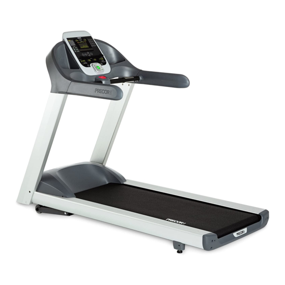
C932i, C946i Treadmill
C932i, C946i Treadmill
Warning: This service manual is for use by Precor trained service providers only.
If you are not a Precor Trained Servicer, you must not attempt to service any Precor Product;
Call your dealer for service.
This document contains information required to perform the majority of troubleshooting, and
replacement procedures required to repair and maintain this product.
This document contains general product information, software diagnostic procedures (when
available), preventative maintenance procedures, inspection and adjustment procedures,
troubleshooting procedures, replacement procedures and electrical block and wiring diagrams.
To move directly to a procedure, click the appropriate procedure in the bookmark section to the
left of this page. You may "drag" the separator bar between this page and the bookmark section
to change the size of the page being viewed.
© 2007 Precor Incorporated
Unauthorized Reproduction and Distribution Prohibited By Law
20077-112
Page 1
20039-112
Advertisement
Table of Contents
Troubleshooting


Need help?
Do you have a question about the C932i and is the answer not in the manual?
Questions and answers