Table of Contents
Advertisement
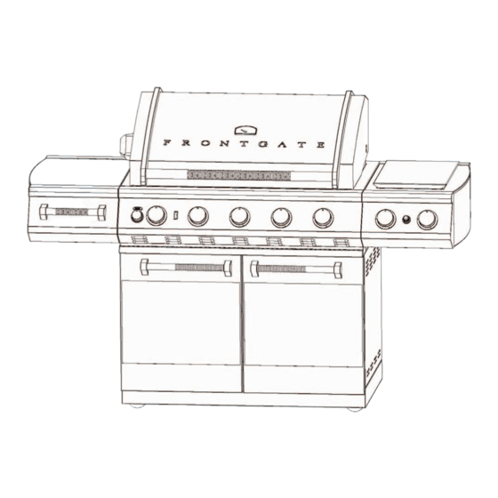
F F r r o o n n t t g g a a t t e e 3 3 8 8 " " P P r r o o f f e e s s s s i i o o n n a a l l G G r r i i l l l l
MODEL NUMBERS:
FG388LP-SD, FG388LP-GD, FG388NG-SD, FG388NG-GD
CINMAR ITEM NUMBERS:
28423 STS LP, 28423 GLA LP, 28423 STS NG, 28423 GLA NG
O O U U T T D D O O O O R R G G R R I I L L L L S S
Installation Instructions and Use & Care Guide
Advertisement
Table of Contents

Related Manuals for Frontgate FG388LP-SD

Summary of Contents for Frontgate FG388LP-SD
- Page 1 F F r r o o n n t t g g a a t t e e 3 3 8 8 " " P P r r o o f f e e s s s s i i o o n n a a l l G G r r i i l l l l MODEL NUMBERS: FG388LP-SD, FG388LP-GD, FG388NG-SD, FG388NG-GD CINMAR ITEM NUMBERS:...
- Page 2 FRONTGATE Thank you for purchasing the Frontgate Professional Grill to meet your grill needs. We're confident your new grill will provide you excellent performance, lasting value, and many years of enjoyment. For future reference, please record your Frontgate Grill purchase:...
-
Page 3: Table Of Contents
TABLE OF CONTENTS Table of Contents..............1 General Safety Information. -
Page 4: General Safety Information
GENERAL SAFETY INFORMATION continued TESTED IN ACCORDANCE WITH ANSI Z21.58b CSA 1.6b-2006 STANDARD FOR OUTDOOR COOKING GAS APPLIANCE. THIS GRILL IS FOR OUTDOOR USE ONLY. Grill Installation Codes Check your local building codes for the proper method of installation, in the absence of local codes, this unit should be installed in accordance with the National Fuel Gas Code, ANSI Z223.1/NFPA 54, Storage and Handling of Liquefied Petroleum Gases, ANSI / NFPA B19.2 or CSA B149.1 Natural Gas and Propane installation code, and the National Electrical Code, ANSI / NFPA 70. - Page 5 GENERAL SAFETY INFORMATION continued PROPER PLACEMENT AND CLEARANCE LP - GAS SUPPLY SYSTEM OF GRILL A 20 lbs tank of approximately 12 1/4 inches in diameter by • 18 1/4 inches high is the maximum size LP gas tank to use. Never use your gas grill in a garage, porch, shed, breezeway or •...
- Page 6 GENERAL SAFETY INFORMATION continued ROTISSERIE DRIVE MOTOR - USE ONLY FOR OUTDOORS, DO NOT EXPOSE TO RAIN. CAUTION: TO ENSURE CONTINUED PROTECTION AGAINST RISK OF ELECTRIC SHOCK, CONNECT TO PROPERLY GROUNDED OUTLETS ONLY, TO REDUCE THE RISK OF ELECTRIC SHOCK, KEEP EXTENSION CORD CONNECTION DRY AND OFF THE GROUND.
- Page 7 GENERAL SAFETY INFORMATION continued • DO NOT heat unopened food containers. A build-up of pressure may cause the containers to burst. • Use an oven mit when opening the grill lid. • NEVER lean over an open grill. • When lighting a burner, pay close attention to what you are doing. Make certain you are aware of which burner you are lighting, so your body and clothing remain clear of any open flames.
-
Page 8: Grill Features
Grill Features 11. LP Rollout Tank Tray 1. Roll Top Hood ( For LP Grills only ) 2. Rotis Motor 3. Side Shelf - Left 12. Drip Tray 4. Utensil Drawer 13. Rotis Meat Fork Storage Slot 5. Towel Bar 14. -
Page 9: Installation Instructions
INSTALLATION INSTRUCTIONS Make sure all packing material is removed from the grill, including the burner tie-down straps. ELECTRONIC IGNITION BATTERY INSTALLATION The electronic ignition required one AA battery be installed to operate. To install the battery included with the grill: 1) Remove the battery box housing by loosening the threaded cap; 2) Install the battery with the positive pole facing toward you;... - Page 10 INSTALLATION INSTRUCTIONS SIDE SHELF WITH UTILITY DRAWER 1. Locate uninstalled side shelf with utility drawer, and remove packaging materials. 2. Pull the drawer all the way out from shelf. Press the drawer slide release levers, and remove drawer. (See Fig. 1 & 2) 3.
-
Page 11: Gas Requirements
LP to Natural Gas or vice versa, the conversion must be done by a service agent authorized by Frontgate. This conversion will only be warranted if the service is provided by an authorized service agent. All costs associated with a conversion including, but not limited... -
Page 12: Gas Requirements
GAS REQUIREMENTS continued INSTALLATION OF NATURAL GAS The Natural Gas regulator and PVC Gas hose have been factory installed. Connect the other end of the PVC Gas Hose to the house gas line using the quick-connect fitting. LIQUID PROPANE (LP) TANK INSTALLATION The LP Gas Regulator and PVC Gas Hose have been factory installed. -
Page 13: Gas Hook-Up
GAS HOOK UP NEVER CONNECT AN UNREGULATED L.P. GAS HOOK-UP GAS SUPPLY LINE TO THE APPLIANCE. Ensure that the rubber "O" Ring on the LP USE THE REGULATOR/HOSE cylinder valve are in place and that the hose ASSEMBLY SUPPLIED. does not come into contact with the grease tray or the grill head. - Page 14 GAS HOOK UP continued CONNECTION (cont.) TO DISCONNECT L.P. GAS CYLINDER: 1. Turn the burner valves OFF. 5. When connecting regulator assembly to 2. Turn the tank valve OFF fully (turn the valve, hand tighten the quick coupling clockwise to stop). nut clockwise to a complete stop.
-
Page 15: Leak Testing
LEAK TESTING GENERAL Although all gas connections on the grill are leak tested at the factory prior to shipment, a complete gas tightness check must be performed at the installation site due to possible mishandling in shipment, or excessive pressure unknowingly being applied to the unit. Periodically check the whole system for leaks following the procedures listed below. -
Page 16: Grill Lighting Instructions
GRILL LIGHTING INSTRUCTIONS TO LIGHT THE MAIN GRILL BURNER(S): Make sure all knobs are "OFF" then turn on the gas supply from the LP tank. Always keep your face and body as far from the grill as possible when lighting. Your grill has an exclusive built-in ignition. - Page 17 GRILL LIGHTING INSTRUCTIONS continued FLAME CHARACTERISTICS Check for proper burner flame characteristics. Burner flames should be blue and stable with no yellow tips, no excessive noise, or lifting. If any of these conditions exist call our customer service line. If the flame is yellow, it indicates insufficient air. If the flame is noisy and tends to lift away from the burner, it indicates too much air.
- Page 18 GRILL LIGHTING INSTRUCTIONS continued TO LIGHT THE SEARING BURNER: 1. Push and hold the Searing Burner control knob for about 5 seconds without rotating. This will allow time for the gas to flow into the searing burner. 2. Turn the knob to the "HI" position and the igniter will click to light the burner. If the burner does not light in 4 seconds turn the control knob to "OFF".
-
Page 19: Match Lighting Instructions
MATCH LIGHTING INSTRUCTIONS TO MATCH LIGHT THE GRILL: Locate Match Extender Lighting Rod found inside left grill door. NOTE: If you have just attempted to light the burner with the igniter, allow 5 minutes for any accumulated gas to dissipate. Simply place a match between the coils on the end of the extension rod. -
Page 20: Rotisserie Installation
ROTISSERIE INSTALLATION Locate the rotisserie bracket on the left hand side of the grill. Slide the rotisserie motor onto the rotisserie bracket. Plug the rotisserie motor into a 110/120 volt electric supply GFI receptacle (6.5 amp min.) Left-hand Right-hand Fork Fork ROTISSERIE OPERATING INSTRUCTIONS Before using the rotisserie, be sure to obtain a pair of grill mitts. -
Page 21: Rotisserie Lighting Instructions
ROTISSERIE LIGHTING INSTRUCTIONS TO LIGHT THE ROTISSERIE BURNER: 1. Push and hold the Rotisserie Burner control knob for about 5 seconds without rotating. This will allow time for the gas to flow into the Rotisserie burner. 2. Turn the knob to the "HI" position and the igniter will click to light the burner. If the burner does not light in 4 seconds turn the control knob to "OFF". -
Page 22: Care And Maintenance
CARE AND MAINTENANCE STAINLESS STEEL This grill is made from both rust resistant and non-rusting, non-magnetic stainless steel. There are many different stainless steel cleaners available. Always use the mildest cleaning procedure first, scrubbing in the direction of the grain. Specks of grease can gather on the surfaces of the stainless steel and bake on to the surface and give the appearance of rust. -
Page 23: Care And Maintenance
CARE AND MAINTENANCE continued SPIDER AND INSECT WARNING! Spiders and small insects may occasionally spin webs or make nests in the grill burner tubes during transit and warehousing. These webs can lead to gas flow obstruction which could result in a fire in and around the burner tubes. -
Page 24: Troubleshooting
TROUBLESHOOTING If the grill does not function properly, use the following check list before contacting our cus- tomer service department. PREHEATING: The grill lid should be in a closed position during the preheat time period. It is necessary to preheat the grill for approximately 10 minutes before cooking. There is no need to pre-heat for casseroles or other foods that require slow cooking. - Page 25 TROUBLESHOOTING continued PROBLEM SOLUTION • Make sure you have the gas turned ON. • Make sure it has a spark while you are trying When I light the grill it does not to ignite the burner. flame immediately. • Push the knob in for approximately 2-3 seconds before turning to ignite the grill.
-
Page 26: Ordering Replacement Parts Instructions
TROUBLESHOOTING continued PROBLEM SOLUTION • Ensure the temperature gauge is functioning properly. Hold a flame to the probe or compare the grill gauge to an oven thermometer place in the grill. • Ensure correct start procedure. Prior to lighting grill, the gas control knobs should be off. -
Page 27: Grill Parts
LIQUID PROPANE (LP) COMPONENTS GRILL PARTS DIAGRAM SEE PAGE 27-28 FOR PARTS LIST LIQUID PROPANE (LP) MODELS... -
Page 28: Grill Parts
NATURAL GAS (NG) COMPONENTS GRILL PARTS DIAGRAM SEE PAGE 27-28 FOR PARTS LIST NATURAL GAS (NG) MODELS... - Page 29 DETAILED PARTS LIST REF. NO. PART NO. DESCRIPTION ORDER QTY. FCFG3808001 FG38 Hood Assembly FCFG3808002 Temperature Gauge FCFG3808003 Back Rotisserie Cover FCFG3808004 Left Light Assembly FCFG3808005 Back Rotisserie Burner FCFG3808006 Right Light Assembly FCFG3808007 Spit Fork (one each) FCFG3808008 Spit Rod FCFG3808009 Warming Rack FCFG3808010...
- Page 30 DETAILED PARTS LIST continued REF. NO. PART NO. DESCRIPTION ORDER QTY. 37 LP FCFG3808064 Side Burner Valve & Manifold Assy. - LP GRILLS ONLY FCFG3808065 Side Burner Valve & Manifold Assy. - NG GRILLS ONLY 37 NG FCFG3808039 Rear Side Burner Flex Line FCFG3808040 Front Side Burner Flex Line FCFG3808041 Main Control Knob &...
-
Page 31: Warranty
Frontgate at its option, will repair or replace this product or any component of the product found to be defective during the warranty period. Replacement may be made with a similar product of equal value. This warranty is valid for the original retail purchaser from the date of initial retail purchase and is not transferable.
Need help?
Do you have a question about the FG388LP-SD and is the answer not in the manual?
Questions and answers