Table of Contents
Advertisement
Advertisement
Table of Contents

Subscribe to Our Youtube Channel
Related Manuals for DaytonAudio SPA1200DSP


Summary of Contents for DaytonAudio SPA1200DSP
- Page 3 FCC Statement 1. This device complies with Part 15 of the FCC Rules. Operation is subject to the following two conditions: (1) This device may not cause harmful interference. (2) This device must accept any interference received, including interference that may cause undesired operation.
-
Page 4: Table Of Contents
Operating Guide: Dayton Audio SPA1200/2400DSP Subwoofer Power Amplifiers Table of Contents Back panel and input/output (I/O) definition ............5 SPA1200DSP and SPA2400DSP wiring ..............6 Feature control-panel key ..................7 Amp system block diagram ..................8 Controlling your subwoofer via PC GUI ..............9 Feature menu display .................... -
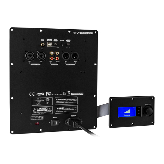
Page 5: Back Panel And Input/Output (I/O) Definition
Back panel and input/output (I/O) definition 1. SPDIF coaxial input: Select between digital SPDIF and analog (XLR or RCA) audio inputs by navigating to and electing desired “Input Source”, via the amp’s dedicated feature control menu knob or software GUIs. 2. -
Page 6: Spa1200Dsp And Spa2400Dsp Wiring
SPA1200DSP and SPA2400DSP wiring SPA1200DSP SPA2400DSP - NOTE: Do NOT bridge outputs. Dual voice coil and dual driver loads only! -
Page 7: Feature Control-Panel Key
Feature control-panel key • Power ON LED: Green LED when amp is operating normally • Standby (STB ) LED: Red when amp is in energy saving “stand by” state • LIMIT LED (Yellow): Lit when Limiter is active • FEATURE SETUP: Single knob digital actuator with single/double-click enabled with rotary scrolling to navigate the amp’s extensive feature menu. -
Page 8: Amp System Block Diagram
Amp system block diagram SPA2400DSP... -
Page 9: Controlling Your Subwoofer Via Pc Gui
DSP processing block diagram Controlling your subwoofer via PC GUI The PC GUI (literally, “Personal Computer, Graphical User Interface”) is the primary mode to access and adjust the DSP for subwoofer optimization. Follow all safe practices and contact Dayton Audio if you require assistance. - Page 10 • USB Link Indicator: When communication via USB with amp is successful, the GUI’s “LED” indicator will light blue. Otherwise, the “LED” stays dark. • Processing Selection: Selecting any icon can effect change in near-real time (NRT) to the amp’s audio outputs. •...
- Page 11 Custom algorithms apply intelligent multi-band room equalization (iEQ™) The included 20Hz-capable iEQ microphone allows estimation of your room’s natural frequency response characteristics and precisely applies PEQ filters to compensate for inevitable response anomalies. Plug the microphone’s 3.5mm “male” fitting into the amp panel’s “female” jack labeled “Mic In” for this procedure. Measurement of room acoustics requires moving your EQ mic through the room’s listening and/or viewing “sweet spots”, typically affixed to a photo tri-pod for best acoustical results.
-
Page 12: Feature Menu Display
Control-Panel: Feature Menu Display Volume, Phase, Low-Pass Filter and all other controls are also accessible via the included rotary control. Volume (shown above) is selected by a single click, upon which simple rotation allows 1dB adjustment. A “double-click” brings you back to the main menu. Subsequent rotation of the controller from the main menu navigates you through a series of setup menus. - Page 13 (13)
- Page 15 3. Once the Wi-Fi successfully links to the sub, open the app to remotely control your sub’s amp. Note: If you have not connected your iPhone to the amp, the app will automatically enter “demo mode”. The demo mode is just a demonstration of each function.
-
Page 16: Firmware Update Guide
Firmware Update Guide: Bug fixes or feature improvements may be introduced via Dayton Audio “firmware” updates. Use this procedure if such an update is provided to all amp owners: 1. Turn off the amp from the main power switch (next to power cord inlet). 2. - Page 17 5. Load the updated firmware file from your saved location and select which new version by clicking the above “Load File” button: 6. When the firmware update is loaded, the below panel and green “progress bar” will show: (17)
- Page 18 7. Press “UPDATE” and the firmware will begin installation: 8. After installation is complete the panel shows: (18)
- Page 19 9. Press “RUN” or cycle power on your amp and the device will now run the new firmware version! 10. To validate your firmware was successfully updated you can note a new operating system version number “V.X.0X” on amp boot-up. (19)
-
Page 20: Dsp And Performance Specification
DSP Functions Feature Controller (LCD mat rix, single -knob, bezel mounted) a) Volume: Range: 0 ~ -100dB, Step: 1dB b) High pass Filter: o Frequency Select: 31.5Hz ~ 125Hz, Step: 1 / 6 Oct. Slope: Flat/-12dB/-24dB A. Low pass Filter: a) Frequency Range: 31.5Hz ~125Hz, Step: 1 / 6 Oct. - Page 21 @230Vac/60Hz C- Rated power C- 3203W @115Vac/60Hz A- Standby mode A- 0.89W @115Vac/60Hz B- ON mode B- 27.5W @115Vac/60Hz C- Rated power C- 3424W SPA1200DSP SPA2400DSP Control Panel Weight: 4lbs 7.4lbs 0.6lbs Dimension: 10.75”H x 9.5” W x 2.875 D 15.5625”H x 9.5”...
- Page 22 Warranty Information Dayton Audio products are warranted free from defects in material and workmanship for 5 years from date of purchase (see exceptions below). In the rare case of a product failure, please contact your place of purchase or call our Customer Support Department at (937) 743-8248. Warranty Limitations There are no other warranties, either express or implied, that extend the foregoing, and there are no warranties of merchantability or fitness for any particular purpose.
Need help?
Do you have a question about the SPA1200DSP and is the answer not in the manual?
Questions and answers