Table of Contents
Advertisement
Quick Links
UNVENTED (VENT-FREE) GAS LOG HEATER
OWNER'S OPERATION AND INSTALLATION MANUAL
MODELS HDLE2824NRA AND HDLE2824PRA
Also Design-Certified As Vented Decorative Appliances When
WARNING: If the information in this manual is not
followed exactly, a fire or explosion may result causing
property damage, personal injury or loss of life.
— Do not store or use gasoline or other flammable
vapors and liquids in the vicinity of this or any other
appliance.
— WHAT TO DO IF YOU SMELL GAS
• Do not try to light any appliance.
• Do not touch any electrical switch; do not use any
phone in your building.
• Immediately call your gas supplier from a neighbor's
phone. Follow the gas supplier's instructions.
• If you cannot reach your gas supplier, call the fire
department.
— Installation and service must be performed by a quali-
fied installer, service agency or the gas supplier.
INSTALLER: Leave this manual with the appliance.
CONSUMER: Retain this manual for future reference.
For more information, visit www.desatech.com
Not Used With Hand-Held Thermostat Remote
Advertisement
Table of Contents

Related Manuals for Desa HDLE2824NRA


Summary of Contents for Desa HDLE2824NRA
- Page 1 UNVENTED (VENT-FREE) GAS LOG HEATER OWNER’S OPERATION AND INSTALLATION MANUAL MODELS HDLE2824NRA AND HDLE2824PRA Also Design-Certified As Vented Decorative Appliances When Not Used With Hand-Held Thermostat Remote WARNING: If the information in this manual is not followed exactly, a fire or explosion may result causing property damage, personal injury or loss of life.
-
Page 2: Table Of Contents
TABLE OF CONTENTS Safety ..............2 Troubleshooting ..........24 Unpacking............4 Wiring Diagram ..........28 Product Identification ........... 5 Specifications ............ 28 Local Codes............5 Replacement Parts ..........28 Product Features ..........5 Service Hints ............. 28 Air For Combustion and Ventilation ..... 6 Technical Service.......... - Page 3 SAFETy Continued IMPORTANT: Read this owner’s WARNING: Do not use a manual carefully and completely blower insert, heat exchanger before trying to assemble, insert or other accessory not ap- operate or service this heater. proved for use with this heater. Improper use of this heater can cause serious injury or death Due to high temperatures, the...
-
Page 4: Unpacking
SAFETy Continued 3. To prevent performance problems, the 10. To prevent the creation of soot, follow the use of a propane/LP fuel tank of less instructions in Cleaning and Maintenance, than 100 lb. capacity is not recommended page 23. (propane/LP units only). 11. -
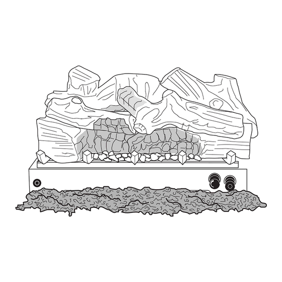
Page 5: Product Identification
PRODUCT IDENTIFICATION 6 Piece Log Set Electronic Ignitor Button Ember Bed Burner Remote Sensor Remote Control with Switch Flame Adjustment Knob Control Knob Figure 1 - Vent-Free Gas Log Heater LOCAL CODES Install and use heater with care. Follow all State of Massachusetts: The installa- local codes. -
Page 6: Air For Combustion And Ventilation
AIR FOR COMBUSTION AND VENTILATION Unusually tight construction is defined as WARNING: This heater shall construction where: not be installed in a room or space a. walls and ceilings exposed to the out- unless the required volume of in- side atmosphere have a continuous water vapor retarder with a rating of one door combustion air is provided perm (6 x 10... - Page 7 AIR FOR COMBUSTION AND VENTILATION Continued Example: Space size 20 ft. (length) x 16 ft. C. Install a lower Btu/Hr fireplace, if lower Btu/ (width) x 8 ft. (ceiling height) = 2,560 cu. ft. Hr size makes room unconfined. (volume of space) If the actual Btu/Hr used is less than the maxi- If additional ventilation to adjoining room mum Btu/Hr the space can support, the space is...
-
Page 8: Installation
AIR FOR COMBUSTION AND VENTILATION Continued Ventilation Air From Outdoors Provide extra fresh air by using ventilation grills Ventilated Outlet or ducts. You must provide two permanent open- Attic ings: one within 12" of the ceiling and one within Outlet 12"... - Page 9 INSTALLATION Continued Carefully follow the instructions below. This CAUTION: This heater creates will ensure safe installation into a masonry, warm air currents. These currents UL127-listed manufactured fireplace or listed vent-free firebox. move heat to wall surfaces next to heater. Installing heater next Minimum Clearances for Side Combustible Material, Side Wall and to vinyl or cloth wall coverings or...
- Page 10 INSTALLATION Continued Minimum Noncombustible Material If Using Mantel Clearances You must have noncombustible material(s) If Not Using Mantel above the fireplace opening. Noncombustible Note: If using a mantel, proceed to If Using materials (such as slate, marble, tile, etc.) Mantel. If not using a mantel, follow the infor- must be at least 1/2"...
- Page 11 INSTALLATION Continued NOTICE: If your installation does not meet the minimum clearances shown, you must do one of the following: • operate the logs only with the flue damper open • raise the mantel to an acceptable height • remove the mantel. Mantel Shelf 10"...
- Page 12 INSTALLATION Continued FLOOR CLEARANCES 1. The fireplace does not meet the clearance to combustibles requirements for vent- A. If installing appliance on the floor level, free operation. you must maintain the minimum distance 2. State or local codes do not permit vent- of 14"...
-
Page 13: Safety Information
INSTALLATION Continued INSTALLING HEATER BASE 1. Apply pipe joint sealant lightly to male threads of the fitting to be threaded into ASSEMBLY gas regulator. Connect approved flexible gas hose to gas regulator of heater (see CAUTION: Do not remove the Figure 11). - Page 14 INSTALLATION Continued CONNECTING TO GAS SUPPLY For propane/LP units, the installer must supply an external regulator. The external WARNING: This appliance regulator will reduce incoming gas pressure. You must reduce incoming gas pressure to requires a 1/2" NPT (National between 11" and 14" of water. If you do not re- Pipe Thread) inlet connection to duce incoming gas pressure, heater regulator the pressure regulator.
- Page 15 INSTALLATION Continued WARNING: Never use an WARNING: Use pipe joint open flame to check for a leak. sealant that is resistant to liquid Apply a noncorrosive leak detec- petroleum (LP) gas. tion fluid to all joints. Bubbles We recommend that you install a sediment forming show a leak.
- Page 16 INSTALLATIONS Continued 2. Pressurize supply piping system by either natural gas (see Figure 17). Apply noncor- opening propane/LP supply tank valve rosive leak detection fluid to gas joints. for propane/LP gas or opening main gas Bubbles forming show a leak. valve located on or near gas meter for 5.
- Page 17 INSTALLATION Continued 7. Disconnect jumper wire from control valve at 11. If logs were removed from heater for TPTH and TH locations (see Figure 19). installing remote accessory, replace logs (see Installing Logs). 8. Install remote receiver into receiver bracket using pads and push button clips Installing Batteries for Remote Receiver provided with receiver (see Figure 20).
- Page 18 INSTALLATION 3. Align holes in bottom of left top log (#3) with pins on top left of front log (#2). Place Continued log on pins (see Figure 25). CAUTION: After installation 4. Align holes in bottom of right top log (#4) with pins on top right of front log (#2).
-
Page 19: Operation
INSTALLATION Continued 6. Add lava rock around base to heater if WARNING: Do not use any desired. Do not place lava rock on logs or burner. Do NOT place lava rock on other ember material not sup- or around front burner. plied with this unit. - Page 20 OPERATION Continued 7. Keep control knob pressed in for 30 sec- NOTICE: During initial operation onds after lighting pilot. After 30 seconds, of new heater, burning logs will release control knob. give off a paper-burning smell. • If control knob does not pop out when Orange flame will also be pres- released, turn off gas supply and contact ent.
- Page 21 OPERATION Continued TO TURN OFF GAS THERMOSTAT SERIES MODEL TO APPLIANCE HRC200 (Included with this Unit) 1. Turn control knob clockwise to the The hand-held remote can be operated using OFF position. either the manual mode (MANU) or thermo- 2a. Set selector switch in the OFF position. static mode (AUTO) (see Figure 30).
-
Page 22: Inspecting Burners
OPERATION Continued Safety Features the room temperature. If the hand-held When away from home for an extended period remote is misplaced, obstructed or for any of time or as a child safety feature to prevent reason cannot transmit to the receiver, the accidental ignition of the fireplace, the receiver receiver will shut off the fireplace. -
Page 23: Cleaning And Maintenance
CLEANING AND MAINTENANCE 5. Blow air into the primary air holes on the WARNING: Turn off heater injector holder. and let cool before cleaning. 6. In case any large clumps of dust have now been pushed into the burner repeat steps 3 and 4. -
Page 24: Troubleshooting
TROUBLESHOOTING WARNING: Turn off heater and let cool before servicing. Only a qualified service person should service and repair heater. CAUTION: Never use a wire, needle or similar object to clean ODS/pilot. This can damage ODS/pilot unit. Note: All troubleshooting items are listed in order of operation. OBSERVED PROBLEM POSSIBLE CAUSE REMEDY... - Page 25 TROUBLESHOOTING Continued OBSERVED PROBLEM POSSIBLE CAUSE REMEDY ODS/pilot lights but flame 1. Control knob not fully 1. Press in control knob fully goes out when control knob pressed in is released 2. Control knob not pressed 2. After ODS/pilot lights, keep in long enough control knob pressed in 30 seconds...
- Page 26 TROUBLESHOOTING Continued OBSERVED PROBLEM POSSIBLE CAUSE REMEDY Moisture/condensation noticed 1. Not enough combustion/ 1. Refer to Air for Combustion on windows ventilation air and Ventilation require- ments (page 6) Heater produces a whistling 1. Turning control knob to HI 1. Turn control knob to LO noise when burner is lit position when burner is position and let warm up...
- Page 27 TROUBLESHOOTING Continued WARNING: If you smell gas • Shut off gas supply. • Do not try to light any appliance. • Do not touch any electrical switch; do not use any phone in your building. • Immediately call your gas supplier from a neighbor’s phone. Fol- low the gas supplier’s instructions.
-
Page 28: Wiring Diagram
• heater will not produce specified heat serial numbers of your heater ready. • propane/LP gas supply may be low You can also visit DESA Heating, LLC’s web You may feel your gas pressure is too low. site at www.desatech.com. -
Page 29: Accessories
LAVA ROCK - GA6060 dealer. If they can not supply these accessories For all models. Order when additional rock call DESA Heating, LLC at 1-866-672-6040 for is desired. information. You can also write to the address DAMPER CLAMP - GA6080 listed on the back page of this manual. -
Page 30: Parts
PARTS MODELS HDLE2824NRA AND HDLE2824PRA 26 (Log Set) www.desatech.com 123741-01C... - Page 31 PARTS This list contains replaceable parts used in your heater. When ordering parts, follow the instructions listed under Replacement Parts on page 28 of this manual. NO. PART NO. DESCRIPTION QTY. Base Assembly • • 119564-01 Rear Burner • • 119563-01 Ember Bed Burner •...
-
Page 32: Warranty
This is DESA Heating, LLC’s exclusive warranty, and to the full extent allowed by law; this express warranty excludes any and all other warranties, express or implied, written or verbal and limits the duration of any and all implied warranties, including warranties of merchantability and fitness for a particular purpose to one (1) year on new products and 30 days on factory reconditioned products from the date of first purchase.
Need help?
Do you have a question about the HDLE2824NRA and is the answer not in the manual?
Questions and answers