Table of Contents
Advertisement
Available languages
Available languages
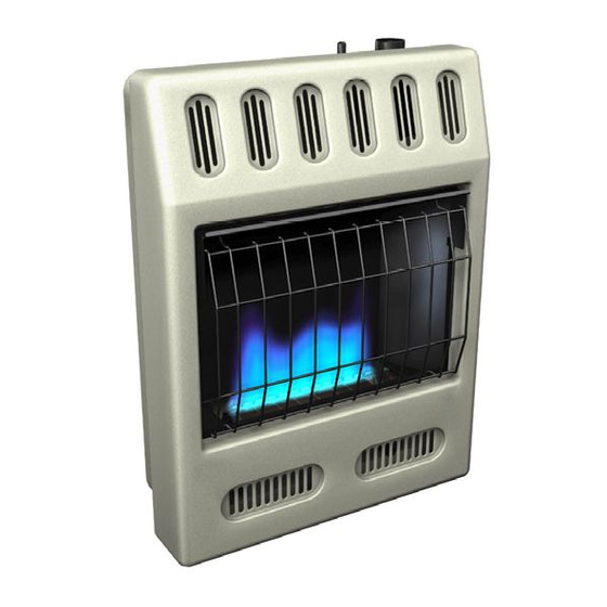
UNVeNTed (VeNT-FRee) BlUe FlAMe GAs HeATeR
sAFeTY INFoRMATIoN ANd INsTAllATIoN MANUAl
lCB20NT, lCB20PT, lCB30NT, lCB30PT
HdB20NT, HdB20PT, HdB30NT, HdB30PT
WARNING: If the information in this manual is not
followed exactly, a fire or explosion may result causing
property damage, personal injury or loss of life.
— Do not store or use gasoline or other flammable
vapors and liquids in the vicinity of this or any other
appliance.
— WHAT TO DO IF YOU SMELL GAS
• Do not try to light any appliance.
• Do not touch any electrical switch; do not use
any phone in your building.
• Immediately call your gas supplier from a neighbor's
phone. Follow the gas supplier's instructions.
• If you cannot reach your gas supplier, call the fire
department.
— Installation and service must be performed by a quali-
fied installer, service agency or the gas supplier.
INSTALLER: Leave this manual with the appliance.
CONSUMER: Retain this manual for future reference.
For more information, visit www.desatech.com
Models
Advertisement
Chapters
Table of Contents

Subscribe to Our Youtube Channel
Related Manuals for Desa LCB20PT


Summary of Contents for Desa LCB20PT
- Page 1 UNVeNTed (VeNT-FRee) BlUe FlAMe GAs HeATeR sAFeTY INFoRMATIoN ANd INsTAllATIoN MANUAl Models lCB20NT, lCB20PT, lCB30NT, lCB30PT HdB20NT, HdB20PT, HdB30NT, HdB30PT WARNING: If the information in this manual is not followed exactly, a fire or explosion may result causing property damage, personal injury or loss of life.
-
Page 2: Table Of Contents
TABle oF CoNTeNTs Safety ..............2 Troubleshooting ..........19 Local Codes............4 Specifications ............ 23 Unpacking............4 Service Hints ............. 23 Product Identification ........... 4 Replacement Parts ..........23 Product Features ..........4 Technical Service..........23 Air For Combustion And Ventilation ..... 5 Service Publications .......... -
Page 3: Safety
sAFeTY Keep the appliance area clear Continued and free from combustible ma- terials, gasoline and other flam- Natural and Propane/LP Gas: Natural and propane/LP gases are fuel gases. Fuel gases mable vapors and liquids. are odorless. An odor-making agent is added 1. -
Page 4: Local Codes
sAFeTY PRodUCT Continued IdeNTIFICATIoN 12. Operating heater above elevations of Control Knob Heater 4,500 feet could cause pilot outage. Ignitor Button Cabinet 13. To prevent performance problems, do not use propane/LP fuel tank of less than 100 lbs. capacity. 14. Provide adequate clearances around air openings. -
Page 5: Air For Combustion And Ventilation
AIR FoR CoMBUsTIoN Unusually Tight Construction The air that leaks around doors and windows ANd VeNTIlATIoN may provide enough fresh air for combustion and ventilation. However, in buildings of un- WARNING: This heater shall usually tight construction, you must provide not be installed in a confined additional fresh air. - Page 6 AIR FoR CoMBUsTIoN 4. Compare the maximum Btu/Hr the space can support with the actual amount of Btu/Hr ANd VeNTIlATIoN used. Continued _______ Btu/Hr (maximum can support) _______ Btu/Hr (actual amount used) DETERMINING FRESH-AIR FLOW Example: FOR HEATER LOCATION 51,200 Btu/Hr (maximum the space can Determining if You Have a Confined or support) Unconfined Space...
-
Page 7: Installation
AIR FoR CoMBUsTIoN Ventilated ANd VeNTIlATIoN Outlet Attic Continued Outlet A ir vENTILATION AIR To Attic Ventilation Air From Inside Building This fresh air would come from an adjoining Crawl Space unconfined space. When ventilating to an Inlet adjoining unconfined space, you must provide Ventilated two permanent openings: one within 12"... - Page 8 INsTAllATIoN CAUTION: This heater cre- Continued ates warm air currents. These INSTALLATION ITEMS currents move heat to wall sur- Before installing heater, make sure you have faces next to heater. Installing the items listed below. heater next to vinyl or cloth wall •...
- Page 9 INsTAllATIoN Front Panel Screw Continued THERMOSTAT SENSING BULB (Thermostat Models Only) The thermostat sensing bulb has been placed below the heater. 1. Place clamp on thermostat sensing bulb as shown in Figure 5. Clamp is provided in hardware package. 2. Snap clamp into upper mounting hole as shown in Figure 5.
- Page 10 INsTAllATIoN Attaching To Wall Anchor Method For attaching mounting bracket to hollow Continued walls (wall areas between studs) or solid walls 2. Mark screw locations on wall (see Figure 8). (concrete or masonry) Note: Only mark last hole on each end of 1.
- Page 11 INsTAllATIoN MOUNTING HEATER TO FLOOR WITH OPTIONAL FLOOR KIT Continued Mounting Base Feet to Heater Installing Bottom Mounting Screws Note: A 90° elbow is required for mounting this 1. Locate two bottom mounting holes. These unit and must be installed BEFORE base feet holes are near bottom on back panel of to provide proper clearance (see Figure 15).
- Page 12 INsTAllATIoN CAUTION: Use only new, Continued black iron or steel pipe. Inter- CONNECTING TO GAS SUPPLY nally-tinned copper tubing may be used in certain areas. Check WARNING: This appliance your local codes. Use pipe of requires a 3/8" NPT (National large enough diameter to allow Pipe Thread) inlet connection to proper gas volume to heater.
- Page 13 INsTAllATIoN CHECKING GAS CONNECTIONS Continued WARNING: Test all gas piping IMPORTANT: Hold the pressure regulator and connections, internal and with wrench when connecting it to gas pip- external to unit, for leaks after ing and/or fittings. Do not over tighten pipe installing or servicing.
- Page 14 INsTAllATIoN Thermostat Gas Valve Continued Test Pressures Equal To or Less Than 1/2 PSIG (3.5 kPa) 1. Close equipment shutoff valve (see Fig- Meter ure 16). 2. Pressurize supply piping system by either opening propane/LP supply tank valve for propane/LP gas or opening main gas valve located on or near gas meter for natural gas or using compressed air.
-
Page 15: Operation
oPeRATIoN 6. Turn control knob counterclockwise to the PILOT position. Press in control FOR YOUR SAFETY READ knob for five (5) seconds. BEFORE LIGHTING 7. With control knob pressed in, push down and release ignitor button. This will light WARNING: If you do not fol- pilot. - Page 16 oPeRATIoN Note: The thermostat sensing bulb mea- sures the temperature of air near the heater Continued cabinet. This may not always agree with room temperature (depending on housing CAUTION: Do not try to ad- construction, installation location, room size, just heating levels by using the open air temperatures, etc.).
-
Page 17: Inspecting Heater
INsPeCTING HeATeR BURNER FLAME PATTERN Check pilot flame pattern and burner flame WARNING: If yellow tipping pattern often. occurs, your heater could pro- PILOT FLAME PATTERN duce increased levels of carbon Figure 21 shows a correct pilot flame pattern. monoxide. Figure 22 shows an incorrect pilot flame pat- tern. -
Page 18: Cleaning
CleANING 1. Shut off the unit, including the pilot. Allow the unit to cool for at least thirty minutes. WARNING: Turn off heater 2. Inspect burner, pilot for dust and dirt. and let cool before cleaning. 3. Blow air through the ports/slots and holes in the burner. -
Page 19: Troubleshooting
TRoUBlesHooTING WARNING: Turn off and unplug heater and let cool before servicing. Only a qualified service person should service and repair heater. CAUTION: Never use a wire, needle or similar object to clean ODS/pilot. This can damage ODS/pilot unit. Note: All troubleshooting items are listed in order of operation. OBSERvED PROBLEM POSSIBLE CAUSE REMEDY... - Page 20 TRoUBlesHooTING Continued OBSERvED PROBLEM POSSIBLE CAUSE REMEDY ODS/pilot lights but flame 1. Control knob not fully 1. Press in control knob fully goes out when control knob pressed in is released 2. Control knob not pressed in 2. After ODS/pilot lights, keep long enough control knob pressed in 30 seconds...
- Page 21 TRoUBlesHooTING Continued OBSERvED PROBLEM POSSIBLE CAUSE REMEDY Yellow flame during burner 1. Not enough air 1. Check burner for dirt and de- combustion bris. If found, clean burner (see Cleaning, page 18) 2. Gas regulator defective 2. Replace gas regulator 3.
- Page 22 TRoUBlesHooTING Continued WARNING: If you smell gas • Shut off gas supply. • Do not try to light any appliance. • Do not touch any electrical switch; do not use any phone in your building. • Immediately call your gas supplier from a neighbor’s phone. Fol- low the gas supplier’s instructions.
-
Page 23: Specifications
PUBlICATIoNs You can purchase a service manual from the address listed on the back page of this manual. Send a check for $5.00 payable to DESA Heat- ing Products. 121254-01A www.desatech.com... -
Page 24: Parts
PARTs MODELS LCB20NT, LCB20PT, LCB30NT, LCB30PT HDB20NT, HDB20PT, HDB30NT, HDB30PT www.desatech.com 121254-01A... - Page 25 PARTs This list contains replaceable parts used in your heater. When ordering parts, follow the instructions listed under Replacement Parts on page 23 of this manual. NO. PART NO. DESCRIPTION QTY. 097159-04 Piezo Ignitor • • • • • • •...
-
Page 26: Accessories
Purchase these heater accessories from your local dealer. If they can not supply these acces- sories, either contact your nearest Parts Central (see page 27) or call DESA Heating Products at 1-866-672-6040 for referral information. You can also write to the address listed on the back page of this manual. -
Page 27: Parts Centrals
PARTs CeNTRAls These Parts Centrals are privately owned businesses. They have agreed to support our customer’s needs by providing original replacement parts and accessories. Those Heater Guys Washer Equipment Co. 255 E. Stowell Street 1715 Main Street Upland, CA 91786 Kansas City, MO 64108 909-982-3011 KS, MO, AR... -
Page 28: Warranty
WARRANTIes FoR NeW ANd FACToRY ReCoNdITIoNed PRodUCTs New Products: DESA Heating, LLC warrants this heater and any parts thereof, to be free of defects in materials and workmanship for two (2) years from the date of first purchase, when operated and maintained in accordance with the manufacturer's instructions. - Page 29 CALENTADOR DE GAS DE LLAMA AZUL NO VENTILADO (SIN VENTILAS) INFORMACIÓN DE SEGURIDAD Y MANUAL DE INSTALACIÓN MODELOS LCB20NT, LCB20PT, LCB30NT, LCB30PT HDB20NT, HDB20PT, HDB30NT, HDB30PT ADVERTENCIA: si la información contenida en este manual no se sigue al pie de la letra, se pueden producir un incendio o una explosión que podría ocasionar da-...
- Page 30 TABLA DE CONTENIDO Seguridad............. 2 Solución de problemas ........19 Códigos.locales............ 4 Especificaciones..........23 Identificación del producto........4 Consejos para servicio........23 Desempaque............4 Piezas de repuesto..........23 Características del producto......... 4 Servicio técnico..........
-
Page 31: Seguridad
SEGURIDAD La superficie del calentador alcanza Continuación temperaturas muy altas cuando éste está funcionando. Mantenga a los PELIGRO: ¡la intoxicación niños y a los adultos alejados de con monóxido de carbono puede las superficies calientes para evitar resultar en la muerte! quemaduras o que la ropa se queme. -
Page 32: Códigos.locales
SEGURIDAD IDENTIFICACIÓN DEL PRODUCTO Continuación 6.. Mantenga limpias y libres de residuos todas las Perilla.de. Gabinete del Botón.de. aberturas de las partes anterior e inferior del control calentador encendido calentador. Esto asegurará que haya suficiente aire para lograr una combustión adecuada. 7.. -
Page 33: Aire Para Combustióny Ventilación
AIRE PARA COMBUSTIÓN Construcción inusualmente sellada El aire que se filtra por los bordes de las puer- Y VENTILACIÓN tas y ventanas puede proporcionar suficiente aire fresco para la combustión y la ventilación. ADVERTENCIA: este calentador Sin embargo, en los edificios que tienen una no debe instalarse en un espacio construcción inusualmente sellada, tiene que confinado ni en una construcción... - Page 34 AIRE PARA COMBUSTIÓN Ejemplo: 51,200 BTU/h (cantidad máxima que el espacio puede admitir) Y VENTILACIÓN 60,000 BTU/h (cantidad real de Continuación BTU/h que se utiliza) El espacio del ejemplo anterior es un espacio confi- DETERMINACIÓN DEL FLUJO DE AIRE nado, ya que la cantidad real de BTU/h que se utiliza FRESCO PARA UBICAR EL CALENTADOR es mayor que la cantidad máxima de BTU/h que el Cómo determinar si tiene un espacio...
-
Page 35: Instalación
AIRE PARA COMBUSTIÓN INSTALACIÓN Y VENTILACIÓN AVISO: este calentador está Continuación diseñado para utilizarse como calefacción adicional. Use este calentador junto con su sistema 30.5 cm de calefacción principal. No (12") instale este calentador como fuente de calefacción principal. Rejillas de ventilación hacia Rejillas de Si tiene un sistema de calefac- una habitación adyacente,... - Page 36 INSTALACIÓN PRECAUCIÓN: este calentador Continuación crea corrientes de aire caliente. ARTÍCULOS DE INSTALACIÓN Estas corrientes mueven el calor Antes de instalar el calentador, asegúrese de hacia la superficie de las paredes tener los elementos que se indican a conti- nuación. próximas al calentador.
- Page 37 INSTALACIÓN Panel.anterior Tornillo Continuación Para mayor comodidad y eficiencia, instale el.calentador • donde haya fácil acceso para la operación, inspección y reparación • en la parte más fría de la habitación Si está planeando utilizar el ventilador, sitúe el calentador cerca de un enchufe eléctrico. BULBO SENSOR DE TERMOSTATO (Sólo para modelos de termostato) El bulbo sensor de termostato se ubica en la...
- Page 38 INSTALACIÓN Método de fijación a anclajes de pared Para fijar el soporte de montaje en paredes Continuación huecas (el área entre las vigas) o en paredes 2. Marque la ubicación de los tornillos en la sólidas (de concreto o mampostería) pared (consulte la figura 8).
- Page 39 INSTALACIÓN instalar ANTES que las patas de la base para cumplir con las distancias mínimas (consulte Continuación la figura 15, página 13). Instalación de los tornillos de montaje inferiores 1. Coloque el gabinete del calentador en una 1. Localice los dos orificios de montaje infe- mesa sobre su parte posterior, de manera riores.
- Page 40 INSTALACIÓN Para gas propano o LP, el instalador debe proveer un regulador externo. El regulador Continuación externo reducirá la presión del gas entrante. CONEXIÓN AL SUMINISTRO DE GAS Debe reducir la presión del gas entrante de manera que esté entre 11 y 14" de agua. Si no reduce la presión del gas entrante, se pueden ADVERTENCIA: este aparato producir daños al regulador del calentador.
- Page 41 INSTALACIÓN REVISIÓN DE LAS CONEXIONES DE Continuación calentador. Si la trampa de sedimentos no se ADVERTENCIA: pruebe to- instala o se instala incorrectamente, el calen- das las conexiones y tubería de tador podría no funcionar correctamente. IMPORTANTE: sujete el regulador de presión gas, tanto internas como exter- con una llave cuando lo conecte a la tubería nas, para verificar que no haya...
- Page 42 INSTALACIÓN COMPROBACIÓN DE LA PRESIÓN DE LAS CONEXIONES DE GAS DEL CALENTADOR Continuación 1. Abra la válvula de cierre del equipo (con- 4. Revise todas las uniones del sistema de sulte la figura 16). tubería de suministro de gas. Aplique 2.
-
Page 43: Funcionamiento
FUNCIONAMIENTO 4. Gire la perilla de control en dirección de la. manecillas. del. reloj. . hasta. la. POR SU SEGURIDAD, LEA posición OFF (apagado). ESTO ANTES DE ENCENDER 5. Espere cinco minutos a que se disipe el EL CALENTADOR gas. Luego, compruebe que no huela a gas, incluso cerca del piso. - Page 44 FUNCIONAMIENTO FUNCIONAMIENTO DEL CONTROL CON TERMOSTATO Continuación El control termostático que se usa en es- 9. Gire la perilla de control en sentido tos. modelos. es. distinto. de. los. termostatos. contrario. al. de. las. manecillas. del. reloj. convencionales. Los termostatos conven- hasta la temperatura deseada.
-
Page 45: Inspección Del Calentador
INSPECCIÓN DEL PATRÓN DE LA LLAMA DEL CALENTADOR CALENTADOR Revise frecuentemente los patrones de la ADVERTENCIA: si se presen- llama del piloto y de la llama del quemador. ta un color amarillo en las pun- PATRÓN DE LA LLAMA DEL PILOTO tas de las llamas, el calentador La figura 21 muestra un patrón correcto de puede producir niveles elevados... -
Page 46: Limpieza
LIMPIEZA También se recomienda que mantenga el conjunto de tubo y piloto del calentador limpio y libre de polvo y suciedad. Para lim- ADVERTENCIA: apague el piar estas piezas, se recomienda usar aire calentador y deje que se enfríe comprimido a una presión no mayor de 30 antes de limpiarlo. -
Page 47: Solución De Problemas
SOLUCIÓN DE PROBLEMAS ADVERTENCIA: apague y desconecte el calentador y deje que se enfríe antes de darle servicio. Sólo una persona de servicio capacitada debe reparar el calentador o darle servicio. PRECAUCIÓN: nunca utilice un alambre, aguja u objetos parecidos para limpiar el piloto/ODS. - Page 48 SOLUCIÓN DE PROBLEMAS Continuación PROBLEMA OBSERVADO CAUSA POSIBLE REMEDIO El piloto con ODS se encien- 1. La perilla de control no está 1. Presione totalmente la pe- de pero la llama se extingue presionada completamente rilla.de.control cuando se suelta la perilla 2.
- Page 49 SOLUCIÓN DE PROBLEMAS Continuación PROBLEMA OBSERVADO CAUSA POSIBLE REMEDIO Llamas.amarillas.durante.la. 1. No hay suficiente aire 1. Revise el quemador en combustión en el quemador busca de polvo y residuos. Si los hay, limpie el quema- dor.(consulte.Limpieza, en la página 18) 2.
- Page 50 SOLUCIÓN DE PROBLEMAS Continuación ADVERTENCIA: si percibe olor a gas, • Cierre el suministro de gas. • No intente encender ningún aparato. • No toque ningún interruptor eléctrico; no use ningún teléfono en el edificio. • Llame inmediatamente a su proveedor de gas desde el teléfono de algún vecino.
-
Page 51: Especificaciones
• Propano o gas LP Central de piezas más cercana (consulte la • Encendido piezoeléctrico página 27), o bien, llame a DESA Heating • Ajuste del regulador de presión: 8" de c.a. Products al 1-866-672-6040 para obtener • Presión del gas de entrada* (pulg. de agua) información de referencia. -
Page 52: Piezas
PIEZAS MODELOS LCB20NT, LCB20PT, LCB30NT, LCB30PT HDB20NT, HDB20PT, HDB30NT, HDB30PT www.desatech.com 121254-01A... - Page 53 PIEZAS Esta lista contiene las piezas reemplazables utilizadas en el calentador. Al hacer un pedido de pie- zas, siga las instrucciones enumeradas en Piezas de repuesto en la página 23 de este manual. N° DE N° PARTE DESCRIPCIÓN CANT. 097159-04 Encendido piezoeléctrico •...
-
Page 54: Accesorios
Si él no puede proveer este accesorio, llame a la Central de piezas. más cercana (consulte la página 27) o llame a.DESA.Heating.Products.al.1-866-672-6040. para obtener información. También puede escribir a la dirección que se encuentra en la última página de este manual. -
Page 55: Central De Piezas
CENTRAL DE PIEZAS Estas Centrales de piezas son empresas privadas. Han aceptado dar asistencia a las nece- sidades de nuestros clientes ofreciendo piezas de repuesto y accesorios originales. Those Heater Guys Washer Equipment Co. 255.E..Stowell.Street 1715.Main.Street Upland, CA 91786, EE.UU. Kansas City, MO 64108, EE.UU. -
Page 56: Garantía
Las piezas de garantía SE DEBEN obtener por medio de los distribuidores autorizados de este producto y de DESA Heating, LLC, quienes proporcionarán las piezas de repuesto originales de fábrica. Si no se utilizan piezas de repuesto originales de fábrica, esta garantía quedará...
Need help?
Do you have a question about the LCB20PT and is the answer not in the manual?
Questions and answers