Table of Contents
Advertisement
Quick Links
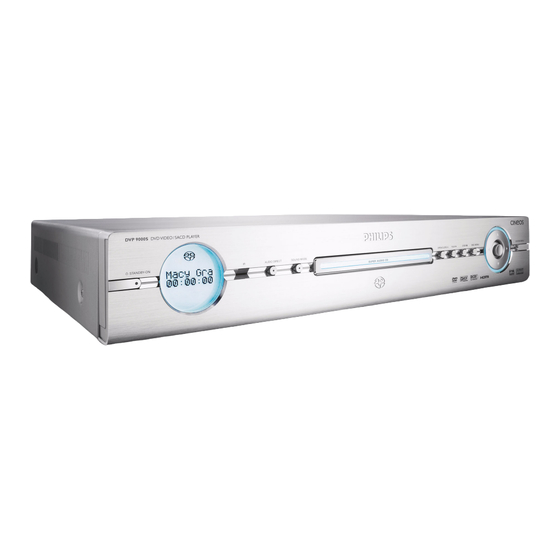
DVD Player
Service
Service
Service
Service
Service
Service Manual
©
Copyright 2004 Philips Consumer Electronics B.V. Eindhoven, The Netherlands
All rights reserved. No part of this publication may be reproduced, stored in a retrieval system or
transmitted, in any form or by any means, electronic, mechanical, photocopying, or otherwise
without the prior permission of Philips.
Published by BB0441 Service AV Systems
Version 1.0
TABLE OF CONTENTS
Location of pc boards & Version variations ................ 1-2
Technical Specifications ............................................. 1-3
Measurement setup .................................................... 1-4
Service Aids, Safety Instruction, etc. ......................... 1-5
Disassembly Instructions & Service positions .............. 2
Diagnostic Software .................................................... 3-1
Software version & upgrade .................................... 3-13
Set Wiring diagram ..................................................... 4-1
PSCAN HDMI Board ..................................................... 5
Front Board .................................................................... 6
AV Board ........................................................................ 7
Module SD5.2 (S) XSA 4FL DV HDMI .......................... 8
Set Mechanical Exploded view & parts list ................... 9
PSU Board (For Information only) ............................... 10
Printed in The Netherlands Subject to modification
DVP9000S/
Page
CLASS 1
LASER PRODUCT
GB
00/69
3139 785 30880
Advertisement
Chapters
Table of Contents

Related Manuals for Philips DVP9000S


Summary of Contents for Philips DVP9000S
- Page 1 LASER PRODUCT © Copyright 2004 Philips Consumer Electronics B.V. Eindhoven, The Netherlands All rights reserved. No part of this publication may be reproduced, stored in a retrieval system or transmitted, in any form or by any means, electronic, mechanical, photocopying, or otherwise without the prior permission of Philips.
-
Page 2: Pscan Hdmi Board
Front Left Board PScan HDMI Board DVD Loader SD5.2 (S) XSA 4FL DV HDMI Board Front Right Board VERSION VARIATIONS: Type /Versions: DVP9000S Features & Board in used: Aux-In Digital In TV-In Audio Out (2 Channel/6 Channel) Digital Out (Coaxial/Optical) - Page 3 SPECIFICATIONS AUDIO FORMAT: GENERAL: MPEG : Compressed Digital Mains voltage : 220-240V for /00 Dolby Digital : 16, 20, 24 bits 110-127V/220-240V for /69 : fs, 44.1, 48, 96 kHz Mains frequency : 50/60Hz MP3 (ISO 9660) : 96, 112, 128, 256 kbps & variable Power consumption : 25W bit rate fs, 32, 44.1, 48 kHz...
- Page 4 MEASUREMENT SETUP Tuner FM Bandpass LF Voltmeter 250Hz-15kHz e.g. PM2534 e.g. 7122 707 48001 RF Generator e.g. PM5326 S/N and distortion meter e.g. Sound Technology ST1700B Use a bandpass filter to eliminate hum (50Hz, 100Hz) and disturbance from the pilottone (19kHz, 38kHz). Tuner AM (MW,LW) Bandpass LF Voltmeter...
- Page 5 SERVICE AIDS Service Tools: Universal Torx driver holder ........4822 395 91019 Torx bit T10 150mm ..........4822 395 50456 Torx driver set T6 - T20 ......... 4822 395 50145 Torx driver T10 extended ........4822 395 50423 Compact Disc: SBC426/426A Test disc 5 + 5A ......
- Page 6 WAARSCHUWING WARNING Alle IC’s en vele andere halfgeleiders zijn All ICs and many other semi-conductors are gevoelig voor electrostatische ontladingen (ESD). susceptible to electrostatic discharges (ESD). Onzorgvuldig behandelen tijdens reparatie kan Careless handling during repair can reduce life de levensduur drastisch doen verminderen. drastically.
-
Page 7: Av Board
DISMANTLING INSTRUCTIONS Dismantling of the DVD Loader Figure 5 1) The tray can be manually open by inserting a screw 4) Loosen 4 screws D (see Figure 5) to remove the DVD driver and push the lever in the direction as shown in Loader (pos 1003-0001). -
Page 8: Service Positions
SERVICE POSITIONS Service position A Service position B PSCAN HDMI Board AV Board Thick Insulation Sheet DVD Loader Thick Insulation Sheet SD5.2 (S) XSA 4FL DV HDMI Board Service position C... - Page 9 Diagnostic Software 1. Definitions and Abbreviations Definitions Control PC Automatic test equipment, part of the production control system in the factory, to control the execution of Diagnostic Nuclei in the DVD player. Diagnostic Nucleus Part of the Diagnostic Software. Each nucleus contains an atomic and software independent diagnostic test, testing a functional part of the DVD player hardware on component level.
- Page 10 During power-on the Selector (part of the DVD boot sequence) will check the presence of certain triggers (signal on Test Pin, key combinations on local keyboard). Via the Selector the appropriate diagnostic mode will be acti- vated: Power-on condition Activate diagnostic mode: Short Description Name used Name used...
- Page 11 certain steps. At the end of the script a message is returned indicating if a failure in one of the modules (Basic Engine, Digital PWB or Display PWB) is detected or not. The message will be displayed on the local display. The test will be done with a closed player and requires equipment for testing audio and video (e.g.
- Page 12 In the overview each Diagnostic Nucleus consists of a reference number, a reference name and remarks. Reference number and name are coupled and one of them is enough for unique identification. Since this document caters to more than one SD module, and not all modules support the same set of test nuclei, a note is placed in the remarks of each test to indicate whether this applies to a specific module or not.
- Page 13 VideoYuvMPEGon Enhanced YUV - Digital Video Colour bar ON VideoScartLo Scart Low (SD5.2 only) VideoScartMi Scart Medium (SD5.2 only) VideoScartHi Scart High (SD5.2 only) VideoScartSwComm Scart Switch communication (SD5.2 only) VideoScartSwDvd Scart Switch Dvd (SD5.2 only) VideoScartSwPass Scart Switch Pass-through (SD5.2 only) VideoScartPinLo PIO-pins used for Scart-switching VideoScartPinMi...
- Page 14 LaserCdOff CD Laser off LaserDvdOn DVD Laser on LaserDvdOff DVD Laser off Furore IC Ref. # Reference Name Remark Furore_SdramWrR Furore SDRAM Write Read test (SD5.2 only) Furore_SdramWrRFast Furore SDRAM interconnection test (SD5.2 only) Furore_Id Furore version ID check (SD5.2 only) Furore_Reset Furore reset (SD5.2 only) Furore_High...
- Page 15 Command Handler The Command Handler handles all commands from the Control PC. Commands will be received as ASCII strings via the RS232 port. All commands received is interpreted by the Command Handler and only correct commands result in the execution of the matching Diagnostic Nucleus. Illegal commands result in an error message to the Control PC. Menu Handler The Menu Handler (part of the Full Diagnostic Software) handles all menus and selections to and from the Service PC.
- Page 16 7. Description of Diagnostic Nucleus Objects BasicSpAcc This is a Basic Diagnostic Nucleus required for correct operation of the Diagnostic Software. Checks and initializes RS232 port and outputs a message that the Diagnostic software has been started. CompProcInfo Reads and display processor specific information. This platform specific function allows the user to read certain registers in the chip at runtime that would be helpful in getting info on the current chip used.
- Page 17 AudioMuteOn, AudioMuteOff Diagnostic Nucleus AudioMuteOn switches the audio mute on. Diagnostic Nucleus AudioMuteOff switches the audio mute off. Correct operation cannot be detected by the Diagnostic Software but must be checked externally. Note: The audio will be muted by the DAC. AudioPinkNoiseOn, AudioPinkNoiseOff Diagnostic Nucleus AudioPinkNoiseOn will generate a pink noise internally on the ZiVa5 chip, which will be passed to the DAC where it is converted to an analogue audio signal.
- Page 18 3-10 DispKeyb (for SD5.2 only) Checks that all keys will be pressed once (arbitrary sequence). Feed back will be given via the local display for each key that has been pressed. DispRc (for SD5.2 only) Displays Header, System and Command code for each received RC code on the local display.. The remote control test can be left by pressing the PLAY key on the local keyboard.
- Page 19 3-11 BeGroovesIn, BeGroovesMid, BeGroovesOut Diagnostic Nuclei BeGroovesIn lets the laser spot jump to the inside limit of the disc. Diagnostic Nuclei BeGroovesMid lets the laser spot jump to the middle of the disc. Diagnostic Nuclei BeGroovesOut lets the laser spot jump to the outside limit of the disc. BeTrayIn, BeTrayOut Diagnostic Nucleus BeTrayIn closes the disc tray.
- Page 20 3-12 DAC_I2C, DAC_I2Cenable, DAC_I2Cdisable (for SD5.2 only) This nucleus checks the interface between the I2C controller on the ZiVa5 and the external DAC board. DAC_ClockInternal, DAC_ClockExternal (for SD5.2 only) These nuclei select the final clock input to the audio DAC. Internal clock means the PCM clock from the monoboard is used.
- Page 21 3) The set display shows [ _ _ _ _ _ _ _ _ ]. 4) Press now successively the following keys: <2> <2> <2> <0> <1> <7> <0> <0> - for DVP9000S/00 <3> <2> <3> <0> <1> <7> <0> <0> - for DVP9000S/69 5) Press button <PLAY>...
- Page 22 1400 1500 1900 Power Supply SD5.2 8106 1010 FRONT PANEL FRONT PANEL 1101 LEFT 1100 1100 RIGHT 1100 SETNAME CLASS_NO DVD VIDEO PLAYER 8622 810 1171 DVP900SA/00 NAME Mak Jee Keen SUPERS. CHECK DATE 2004-10-22 KONINKLIJKE PHILIPS ELECTRONICS N.V. 2000...
-
Page 23: Table Of Contents
TECHNICAL REMARKS PSCAN HDMI BOARD TABLE OF CONTENTS Top View Layout .............. 5-2 Bottom View Layout ............5-3 Circuit Diagram (Part 1) ........... 5-4 Circuit Diagram (Part 2) ........... 5-5 Circuit Diagram (Part 3) ........... 5-6 Circuit Diagram (Part 4) ........... 5-7 Electrical parts list ............ -
Page 24: Top View Layout
PSCAN HDMI BOARD - TOP VIEW LAYOUT This assembly drawing shows a summary of all possible versions. For components used in a specific version see schematic diagram and respective parts list. 3139 243 3080 pt6 dd wk0437... -
Page 25: Bottom View Layout
PSCAN HDMI BOARD - BOTTOM VIEW LAYOUT This assembly drawing shows a summary of all possible versions. For components used in a specific version see schematic diagram and respective parts list. 3139 243 3080 pt6 dd wk0437... -
Page 26: Circuit Diagram (Part 1)
PSCAN HDMI BOARD - CIRCUIT DIAGRAM (PART 1) 2100 A14 3162 D11 2101 A5 3163 E11 2102 A13 3164 D11 2103 A14 3165 D9 +1V8_CORE 5100 P-scan_DeInterlacer 2105 B6 3166 D9 +1V8_CORE DECOUPLING CAP FOR FLI2301/ FLI2310 2106 A5 3167 G10 DECOUPLING CAP FOR FLI2301 / FLI2310 +3V3_D 2107 B14... -
Page 27: Circuit Diagram (Part 2)
PSCAN HDMI BOARD - CIRCUIT DIAGRAM (PART 2) 1000 D1 4201 E2 1001-1 F6 4202 H6 1001-2 I6 4209 G14 1200 B1 4210 H10 +5VD 1203 A4 4211 H2 P-scan_Ext_DAC 7201 +5VD 1210 F3 4213 A13 PCF8574T 2201 I12 4214 B12 4213 INT_ +3V3D_V... -
Page 28: Circuit Diagram (Part 3)
PSCAN HDMI BOARD - CIRCUIT DIAGRAM (PART 3) 1003-A B11 4322 C8 1003-B D11 4323 D8 1003-C E11 4324 F8 1301 D13 4325 I2 P-scan_VideoBuffer 1302 G13 4328 B7 1310 B1 4329 C7 2300 B8 4330 E7 2302 C7 4331 G11 2303 C9 5300 B6 2304 B3... -
Page 29: Circuit Diagram (Part 4)
PSCAN HDMI BOARD - CIRCUIT DIAGRAM (PART 4) 1002 C14 3468 G2 1402 B1 3469 H2 1404 C2 3470-A I6 1405 D2 3470-B I5 1410 A4 3470-C I6 P-scan_HDMI 1411 B2 3470-D I5 2401 A12 3471-A I6 +3V3_D 2402 E12 3471-B I5 7419-1 +3V3_D... -
Page 30: Electrical Parts List
ELECTRICAL PARTS LIST - PSCAN HDMI BOARD ELECTRICAL PARTS LIST - PSCAN HDMI BOARD MISCELLANEOUS 1000 2422 025 17451 FLEX CONNECTOR 30P 5202 4822 157 11716 FXD IND 0805 100MHz 30R 7412 9352 687 20125 IC SM 74LVC1G125GW 1002 2422 033 00505 SOCKET HDMI 19P 5203 4822 157 11716... - Page 31 TECHNICAL REMARKS FRONT BOARD TABLE OF CONTENTS Front Left Board - Top & Bottom View Layout ....6-2 Front Left Board - Circuit Diagram ........6-3 Front Right Board - Top & Bottom View Layout ....6-4 Front Right Board - Circuit Diagram ........ 6-5 Electrical parts list ............
- Page 32 FRONT LEFT BOARD - TOP VIEW LAYOUT This assembly drawing shows a summary of all possible versions. For components used in a specific version see schematic diagram and respective parts list. 3139 243 3135 pt3 dd wk0437 FRONT LEFT BOARD - BOTTOM VIEW LAYOUT This assembly drawing shows a summary of all possible versions.
- Page 33 FRONT LEFT BOARD - CIRCUIT DIAGRAM 1100 A5 1101 E13 1102 C1 1103 F4 STANDBY PANEL 1104 F5 1110 C8 1111 A3 1112 A3 1134 G1 1135 H1 2101 B7 1112 AUDIO DIRECT 2102 B8 2103 D11 2104 E8 1111 SOUND MODE 2105 D9 +LED...
- Page 34 FRONT RIGHT BOARD - TOP VIEW LAYOUT This assembly drawing shows a summary of all possible versions. For components used in a specific version see schematic diagram and respective parts list. 3139 243 3134 pt3 dd wk0437 FRONT RIGHT BOARD - BOTTOM VIEW LAYOUT This assembly drawing shows a summary of all possible versions.
- Page 35 FRONT RIGHT BOARD - CIRCUIT DIAGRAM ELECTRICAL PARTS LIST - FRONT LEFT BOARD ELECTRICAL PARTS LIST - FRONT RIGHT BOARD MISCELLANEOUS MISCELLANEOUS 1100 C1 1202 B2 1204 B4 1206 B4 3201 A2 3203 C2 3205 C3 3207 C4 3209 A4 6201 B2 7208 A3 1001...
- Page 36 BRIEF INTRODUCTION OF THE AV BOARD The AV Board consists of the following features : VIDEO OUTPUT - CVBS - S-Video - Scart RGB (For Europe Model) AUDIO OUTPUT AV BOARD - 2 Channel / 6 Channel - Coaxial / Optical TABLE OF CONTENTS Brief Introduction of the AV Board ........
- Page 37 AV BOARD - TOP VIEW LAYOUT This assembly drawing shows a summary of all possible versions. For components used in a specific version see schematic diagram and respective parts list. 3139 243 3090 pt7 dd wk0437 PART A PART B...
- Page 38 AV BOARD - BOTTOM VIEW LAYOUT This assembly drawing shows a summary of all possible versions. For components used in a specific version see schematic diagram and respective parts list. 3139 243 3090 pt7 dd wk0437 PART A PART B...
- Page 39 AV BOARD - TOP VIEW LAYOUT (PART A) This assembly drawing shows a summary of all possible versions. For components used in a specific version see schematic diagram and respect...
- Page 40 AV BOARD - CIRCUIT DIAGRAM (PART 1) 1102 D7 1103 B9 1400 B2 1401 B1 1402 G1 1403 I2 Digital Audio Master_Clk Generation & Switchng 1404 I1 2100 E2 +3V3D 2101 E2 tive parts list. 3139 243 3090 pt7 dd wk0437 2102 D3 2103 E3 2104 E3...
- Page 41 AV BOARD - CIRCUIT DIAGRAM (PART 2) 1200 F2 2200 A5 2201 A6 2202 A5 2204 B6 AV_VIDEO DAC 2205 B2 2206 C2 This assembly drawing shows a summary of all possible versions. For components used in a specific ve +3V3_DAC +5VA 2207 E2...
- Page 42 AV BOARD - TOP VIEW LAYOUT (PART B) ersion see schematic diagram and respective parts list. 3139 243 3090 pt7 dd wk0437...
- Page 43 AV BOARD - BOTTOM VIEW LAYOUT (PART A) This assembly drawing shows a summary of all possible versions. For components used in a specific version see schematic diagram and respective...
- Page 44 AV BOARD - CIRCUIT DIAGRAM (PART 3) 2365 C1 2366 C1 2367 C2 2368 C2 2369 D1 AV_AUDIO_Front & TV Channels e parts list. 3139 243 3090 pt7 dd wk0437 2370 D1 2371 D2 2372 D2 2373 D3 2374 D3 2375 D3 2376 D4 7320...
- Page 45 7-10 7-10 AV BOARD - CIRCUIT DIAGRAM (PART 4) 1300 B12 4102 G7 1301-1 F12 4107 E2 2301 B5 4108 F2 2302 B5 4109 G2 2303 B5 4110 H2 AV_AUDIO_Front & TV Channels 2305 B4 4301 C6 2306 B3 4302 D6 2307 B2 4303 E2 2308 C6...
- Page 46 7-11 7-11 AV BOARD - BOTTOM VIEW LAYOUT (PART B) version see schematic diagram and respective parts list. 3139 243 3090 pt7 dd wk0437...
- Page 47 7-12 7-12 AV BOARD - CIRCUIT DIAGRAM (PART 5) 1301-2 C12 7401-B C4 2401 A5 7402-A E4 2402 A5 7402-B G4 2404 B5 7404 C9 AV_AUDIO_C/FE & Surround Channels 2405 B4 7405 D9 2406 B2 7406 E9 2407 B2 7407 F9 2408 B5 7408 C11 AVCC_C...
- Page 48 7-13 7-13 AV BOARD - CIRCUIT DIAGRAM (PART 6) 1500 E1 4513 I2 1501 A3 4514 J11 1502 F14 4515 F10 1503 G14 4516 F11 1504 I13 5503 H11 AV_VIDEO 3554 2500 A12 5504 I9 2501 B12 5505 I12 7516 2516 2502 A9 6500 B5...
- Page 49 7-14 7-14 AV BOARD - CIRCUIT DIAGRAM (PART 7) 1600 A7 3663 A4 1601 A6 3664 B4 2600 B12 3665 D3 2603 C13 3666 D6 2604 C12 3667 E4 2605 C11 3669 H7 2606 E13 3670 G7 2607 E13 3671 G7 1601 1600 PH-B...
- Page 50 7-15 7-15 ELECTRICAL PARTS LIST - AV BOARD ELECTRICAL PARTS LIST - AV BOARD MISCELLANEOUS 0004 3139 241 00071 SPRING SCART 5601 2422 535 94092 FXD IND SM 0805 33U 20% 7502 9352 456 80115 IC SM 74HCT1G125GW 0005 3139 241 00071 SPRING SCART 5602 2422 535 94092...
- Page 51 TECHNICAL REMARKS MODULE SD5.2 (S) XSA 4FL DV HDMI TABLE OF CONTENTS Top View Layout .............. 8-2 Top & Bottom View Layout Mapping ....... 8-3 Bottom View Layout ............8-4 Circuit Diagram (Part 1) ........... 8-5 Circuit Diagram (Part 2) ........... 8-6 Circuit Diagram (Part 3) ...........
- Page 52 TOP VIEW LAYOUT This assembly drawing shows a summary of all possible versions. For components used in a specific version see schematic diagram and respective parts list. 3139 243 3137 pt4 dd wk0439...
-
Page 53: Top View Layout
TOP VIEW LAYOUT MAPPING BOTTOM VIEW LAYOUT MAPPING... -
Page 54: Bottom View Layout
BOTTOM VIEW LAYOUT This assembly drawing shows a summary of all possible versions. For components used in a specific version see schematic diagram and respective parts list. 3139 243 3137 pt4 dd wk0439... -
Page 55: Circuit Diagram (Part 1)
CIRCUIT DIAGRAM (PART 1) 1101 I1 3173 I4 2100 E3 3175 H5 2103 C12 3176 I8 2104 C12 3177 H5 3V3B 2105 C13 3178 I8 5110 DVD DECODER 2106 C13 3180 H4 2107 C13 3181-A I9 7104 2108 C13 3181-B I9 FXO-31FL 2109 C14 3181-C I9... -
Page 56: Circuit Diagram (Part 2)
CIRCUIT DIAGRAM (PART 2) 1200 C1 2200 A9 2201 A3 2202 A6 2203 C9 FLASH MEMORY UPD(0:15) ZIVA_HOST 2204 D9 FL3V3B FL3V3B 2205 D4 2201 100n 2202 100n 2206 D7 2207 E2 FL3V3B GNDB GNDB 2208 E4 2200 100n 2210 E1 UPA(1) UPD(0) UPA(1) -
Page 57: Circuit Diagram (Part 3)
CIRCUIT DIAGRAM (PART 3) 2301 F4 2302 F4 2303 F5 2304 F5 ZIVA SDRAM 2305 F5 2307 F5 3V3B 3V3B 2308 F6 2309 F6 3300 2310 F6 SD13V3 3V3B 2311 F6 2312 A10 5300 2314 B4 SD33V3 2316 E5 SD23V3 3V3B 3V3B 2317 E6... -
Page 58: Circuit Diagram (Part 4)
CIRCUIT DIAGRAM (PART 4) 1400 C13 2400 B1 2401 B2 2402 B2 2404 B2 FURORE AND SACD INTERFACE 2405 B2 2406 B3 2407 B4 2408 B5 2409 B5 1V8S 2410 B5 2411 B5 2412 B6 3V3S A1V8S 2413 B6 2414 B8 2415 B9 2416 B9 2417 D13... -
Page 59: Circuit Diagram (Part 5)
CIRCUIT DIAGRAM (PART 5) 1500 B13 3537 B13 1501 B1 3538 F2 1502 C11 3539 G2 1503 C11 3541 F11 V5VB 1504 D11 3542 G11 VIDEO FILTER - A/V I/F 2500 A6 3544 F9 2501 A7 3546 H8 2503 A6 3547 G8 2504 A7 3548 G9... -
Page 60: Circuit Diagram (Part 6)
8-10 8-10 CIRCUIT DIAGRAM (PART 6) 1600 B1 5609 B2 1601-1 B10 5613 H2 1601-2 B10 5617 F2 1602 H1 5619 F2 1603 F8 5621 D2 DIGITAL INPUT - HOST I/F - ATAPI I/F - E-LINK 1604 D1 5624 E2 1605 G1 7601 B3 1606 E1... -
Page 61: Circuit Diagram (Part 7)
8-11 8-11 CIRCUIT DIAGRAM (PART 7) 1700 D1 4706 I14 1701 G1 4707 I14 1702 I1 4708 I14 2700 A6 4709 I14 2701 A12 5700 C3 LASER CONTROL M9VF M5VF 2702 A13 5701 D3 2703 A5 5703 I14 2704 A13 5706 A13 RF5VF 2705 B5... -
Page 62: Circuit Diagram (Part 8)
8-12 8-12 CIRCUIT DIAGRAM (PART 8) 1800 H5 4813 F4 2800 A5 4817 H3 2801 A6 5800 A1 2802 A6 5802 B1 FRONT END CONTROLLER 2803 A6 7800 B11 2804 A7 7801 D7 2805 A7 7802-A F10 2806 A8 7802-B F10 2808 A8 7802-C G10 2800... -
Page 63: Circuit Diagram (Part 9)
8-13 8-13 CIRCUIT DIAGRAM (PART 9) 1900 B1 1901 B7 2900 A3 2901 A4 POWER SUPPLY 2904 C2 2905 C2 2906 D7 7903 M9VF 2907 C4 LD1117S18 2908 D4 6900 6901 6902 6903 5915 5911 2909 E4 2910 D6 5912 100MHZ 2911 F4 2912 C5... - Page 64 8-14 8-14 PARTS LIST - MODULE SD5.2 (S) XSA 4FL DV HDMI ELECTRICAL PARTS LIST - SD5.2 (S) XSA 4FL DV HDMI BOARD 0001 3139 248 72052 LOADER A97SL ACTIMA SILVER 5501 4822 157 70299 FXD IND SM 1210 2,2uH 5% 7300 9322 196 10668 IC SM MT48LC8M16A2TG-6A...
- Page 65 SET MECHANICAL EXPLODED VIEW * For /00 version only Exploded View_3139 249 25481_dd wk0437...
-
Page 66: Parts List
MECHANICAL & ACCESSORIES PARTS LIST - MAIN UNIT SCREW LISTS - MAIN UNIT 0101 3139 241 60092 PANEL ORNAMENTAL AL D3 x 10 0103 3139 244 05552 CABINET FRONT D3 x 10 0105 3139 244 05541 BUTTON PWR STDBY CHROME D3 x 10 0107 3139 244 05531... -
Page 67: Psu Board (For Information Only)
10-1 PSU BOARD (For Information only) It is not recommended for component repair on this board but to replace the board when it becomes defective. Therefore no service parts list is published in this chapter. The only service part available for replacement is: Module PSU BIL PERF2003 WR HE .... - Page 68 10-2 10-2 PSU BOARD - CIRCUIT DIAGRAM +12V 2.5uH 220R 1/2W UF2004 EL-25 SPARK GAP 9435 200K/1206 200K/1206 22K/0603 T2A/250V 104/0603 100u/25V 102/1KV CON1 1.5M/1206 330u/25V/L.ESR 1N4007 1N4007 2SC945 102/1KV ZNR1 10K/0603 2K2/1206 471V 100u/400V 0.22u/300V 2P/7.92mm +5.1V 1N4007 1N4007 FR107 2.5uH 1.5M/1206...
Need help?
Do you have a question about the DVP9000S and is the answer not in the manual?
Questions and answers