Table of Contents
Advertisement
Available languages
Available languages
Quick Links
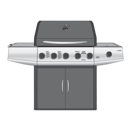
Parrilla a Gas de 5 Quemadores
OWNER'S MANUAL / MANUAL DEL PROPIETARIO
GUARDE ESTE MANUAL PARA REFERENCIA FUTURA
Model / Modelo 810-2545-C/810-2546-C
NOTICE TO INSTALLER:
LEAVE THESE INSTRUCTIONS
WITH THE GRILL OWNER FOR
FUTURE REFERENCE .
AVISO PARA EL
INSTALADOR:
ENTREGUE ESTAS
INSTRUCCIONES AL
PROPIETARIO DE LA PARRILLA
PARA REFERENCIA FUTURA.
5 Burner Gas Grill
ASSEMBLY AND OPERATING IN STRUC TIONS
INSTRUCCIONES DE ARMADO Y OPERACIÓN
SAVE THIS MANUAL FOR FUTURE REFERENCE
HAZARDOUS EXPLOSION MAY RESULT IF THESE WARNINGS AND INSTRUCTIONS
ARE IGNORED. READ AND FOLLOW ALL WARNINGS AND INSTRUCTIONS IN THIS
MANUAL TO AVOID PERSONAL INJURY, INCLUDING DEATH OR PROPERTY DAMAGE.
SE PUEDE PRODUCIR UNA EXPLOSIÓN PELIGROSA SI SE HACE CASO OMISO A
ESTAS ADVERTENCIAS E INSTRUCCIONES. LEA Y SIGA TODAS LAS ADVERTENCIAS
E INSTRUCCIONES EN ESTE MANUAL PARA EVITAR LESIONES PERSONALES,
WARNING/ADVERTENCIA
INCLUSO LA MUERTE, O LOS DAÑOS MATERIALES.
Advertisement
Chapters
Table of Contents

Related Manuals for Grill King 810-2545-C


Summary of Contents for Grill King 810-2545-C
- Page 1 ASSEMBLY AND OPERATING IN STRUC TIONS INSTRUCCIONES DE ARMADO Y OPERACIÓN SAVE THIS MANUAL FOR FUTURE REFERENCE GUARDE ESTE MANUAL PARA REFERENCIA FUTURA Model / Modelo 810-2545-C/810-2546-C WARNING/ADVERTENCIA NOTICE TO INSTALLER: HAZARDOUS EXPLOSION MAY RESULT IF THESE WARNINGS AND INSTRUCTIONS LEAVE THESE INSTRUCTIONS ARE IGNORED.
- Page 2 IMPORTANT SAFETY WARNINGS WE WANT YOU TO ASSEMBLE AND USE YOUR GRILL AS SAFELY AS POSSIBLE. THE PURPOSE OF THIS SAFETY ALERT SYMBOL IS TO ATTRACT YOUR ATTENTION TO POSSIBLE HAZARDS AS YOU ASSEMBLE AND USE YOUR GRILL. WHEN YOU SEE THE SAFETY ALERT SYMBOL PAY CLOSE ATTENTION TO THE INFORMATION WHICH FOLLOWS! READ ALL SAFETY WARNINGS AND INSTRUCTIONS CAREFULLY BEFORE ASSEMBLING AND OPERATING YOUR GRILL.
-
Page 3: Table Of Contents
TABLE OF CONTENTS: General Warnings ..........3-4 LP Gas Cylinder (Tank) Specifi cations and Installation . -
Page 4: General Warnings
GENERAL WARNINGS: WARNING • Leak test all connections before fi rst use, even if grill was purchased fully assembled and after each tank refi ll. Check the propane tank rubber seal for damage. • Always check the grill and propane tank prior to each use as indicated in the “Checking for Leaks”... -
Page 5: Lp Gas Cylinder (Tank) Specifications And Installation
• Grill is hot when in use. To avoid burns: • DO NOT attempt to move the grill. • Block the wheels so the unit does not accidentally move. • Wear protective gloves or oven mitts. • DO NOT touch any hot grill surfaces. •... - Page 6 LP GAS CYLINDER (TANK) SPECIFICATIONS: LP gas cylinder (not supplied with this grill) The LP (Liquid Propane) gas cylinder specifi cally designed to be used with this grill must be 12” (30.5 cm) diameter x 18” (45.7 cm) tall and have a 20 lb. (9.1 kg) capacity incorporating a Type 1 cylinder valve and an over-fi lling protection device (OPD).
-
Page 7: Hose & Regulator Specifications And Installation
LP GAS CYLINDER (TANK) RUBBER SEAL INSPECTION: • Inspect the propane tank valve rubber seal for cracks, wear or deterioration prior to use. A damaged rubber seal can cause a gas leak, possibly resulting in an explosion, fi re or severe bodily harm. •... -
Page 8: Leak Testing
HOSE AND REGULATOR: Your grill is equipped with a Type 1 connection device with the following features: 1. The system will not allow gas fl ow from the cylinder until a positive connection to the valve has been made. Note: The cylinder valve and all grill burner knobs must be turned OFF before any connection is made or removed. -
Page 9: Checking For Leaks
DANGER To prevent fi re or explosion hazard: • DO NOT smoke or permit ignition sources in the area while conducting a leak test. • Perform test OUTDOORS in a well ventilated area that is protected from the wind. • Never perform a leak test with a match or open fl ame. -
Page 10: Pre-Start Check List
PRE-START CHECK LIST: DANGER Property damage, bodily harm, severe burns, and death could result from failure to follow these safety steps. These steps should be performed after the grill has been assembled and prior to each use. DO NOT operate this grill until you have read and understand ALL of the warnings and instructions in this manual. -
Page 11: Lighting The Side Burner
MATCH LIGHTING THE MAIN BURNERS: 1. Open lid before lighting burner. 2. Make sure all control knobs are in the “OFF” position. 3. Place a paper match in the end of the matchlighter. Strike the match and place through lighting hole in the left hand side of the grill to approximately 1/2”... -
Page 12: Operating The Grill
OPERATING THE GRILL: WARNING • Read and follow all warnings and instructions contained in the preceding sections of this manual. • Never use charcoal, lava rocks or wood briquets in a gas grill. Flavoring chips must be contained in a metal smoking box to contain ash and prevent fi res. •... -
Page 13: Using Other Features Of The Grill
ROTISSERIE COOKING: • Your grill was pre-drilled from factory to include mounting holes for a rotisserie (sold separately). Do not use a rotisserie not specifi cally manufactured for this grill. • Read and follow all instructions provided with the rotisserie. Save instructions for future reference. •... -
Page 14: Proper Care And Maintenance
PROPER CARE & MAINTENANCE: WARNING: If a bristle brush is used to clean any of the cooking surfaces, ensure no loose bristles remain on the cooking surfaces prior to grilling as loose bristles may attach to food. CLEANING INTERIOR OF GRILL: •... - Page 15 BURNER ASSEMBLY/MAINTENANCE: • Although your burners are constructed of stainless steel, they may corrode as a result of the extreme heat and acids from cooking foods. Regularly inspect the burners for cracks, abnormal holes, and other signs of corrosion damage. If found, replace the burner.
-
Page 16: Transporting And Storage
BURNER ADJUSTMENT: WARNING • DO NOT attempt to adjust burner air shutter until grill has cooled down for approximately 30 minutes. Failure to do so could cause severe burns. • Normal fl ame should be soft blue with yellow tips between 1 in. - 2 in. when burner is on “HIGH” . Depending on elevation, burner air shutter may need to be adjusted to obtain correct air to fuel ratio. -
Page 17: Trouble Shooting
TROUBLE SHOOTING: Problem Possible Cause Prevention/Cure Burner will not light LP gas tank valve is closed Make sure regulator is securely attached to the LP gas tank, turn LP gas tank valve to “OPEN” LP gas tank is low or empty Check if LP gas tank is empty. -
Page 18: Grill Cooking Tips
Problem Possible Cause Prevention/Cure Flame blows out High or gusting winds Do not use grill in high winds Low on LP gas Replace or refi ll LP gas tank Burner holes may be obstructed Refer to “Burner Assembly/Maintenance” instructions Flow limiting device tripped Refer to “Regulator Resetting Procedure”... -
Page 19: Assembly Instructions
ASSEMBLY INSTRUCTIONS: Make sure you have all items listed under PARTS LIST and PARTS BAG CONTENTS before you begin the installation process. PARTS BAG CONTAINS: Qty. Qty. 32 M6 X 12 mm Bolts (Black) 20 M6 Star Washers (Black) M6 X 12 mm Bolts (Silver) M6 Lock Washers (Silver) M6 X 30 mm Bolts (Black) Plastic Rivets... - Page 20 READ ALL SAFETY WARNINGS & ASSEMBLY INSTRUCTIONS CAREFULLY BEFORE ASSEMBLING OR OPERATING YOUR GRILL. WE RECOMMEND TWO PEOPLE WORK TOGETHER WHEN AS SEM BLING THIS UNIT. The following tools are required to assemble this Grill King 5 Burner Gas Grill: • Screwdriver • Hex Nut Wrench...
- Page 21 (Proof of purchase will be required.) Inspect contents of the box to ensure all parts are included and undamaged.
- Page 22 Choose a good, cleared assembly area and get a friend to help you put your grill together. Lay card- board down to protect grill fi nish and assembly area. CAUTION: Some parts may contain sharp edges. Wear protective gloves if necessary. Step 1 Attach lower cart brace to legs using four M6 X 30 mm bolts (black).
- Page 23 Step 5 Attach the upper cart brace to the side frame using four M6 X 12 mm bolts (black). Tighten securely. Note: With the help of a friend, turn the cart assembly over. Try to minimize the stress to the legs.
- Page 24 Step 7 To attach the door handle to the door, insert two M4 X 10 mm bolts (black) through the door and onto the door handle. Align the bolts to the holes which are located on the door panel. Then tighten the two bolts securely.
- Page 25 Grill Body Assembly Note: When performing Step 10, Lift grill body from front and rear panels to avoid injury to hands and fi ngers. Step 10 With the help of a friend, place grill body assembly on grill cart. Secure using four M6 X 12 mm bolts (black) and M6 star washers (black) on each side of the frame.
- Page 26 Step 11 Insert the two bolts with pre-attached nuts on the left side table into the keyholes on the side table front panel. Tighten the nuts with wrench. Insert one M6 X 12 mm bolt (black) from side table to side table front panel. Attach hooks to side table towel rack bar.
- Page 27 Step 13 Attach side table to left side of cart frame assembly. Place keyholes over pre-attached bolts and slide toward back of grill, then tighten securely. Fasten side table front panel to grill body with one M6 X 12 mm bolt (silver). Step 14 Attach side burner assembly to Burner Venturi...
- Page 28 Step 16 Burner Venturi Firmly seat the valve nozzle into the burner venturi. Hold in place while you perform Step 17 . Side Burner Valve Step 17 Insert the two screws that are already attached on the side burner Valve valve through the corresponding key Nozzle holes on the side burner front panel...
- Page 29 Step 19 Attach side burner igniter lead wire to the electrode as illustrated. Side Burner Igniter Lead Electrode Step 20 Hang grease cup from brackets on bottom of grill body assembly. Grease Cup...
- Page 30 Step 21 Warming Rack Place the heat distribution plates on lower level of grill body assembly directly above burners. Cooking Grills Heat Distribution Plates Step 22 Place cooking grills on support ribs directly above heat distribution plates. Grooves Step 23 Place warming rack in grooves so that it sits above the cooking grills.
- Page 31 Grill King 5 Burner Gas Grill (Assembled)
- Page 32 IMPORTANTES ADVERTENCIAS DE SEGURIDAD ES NUESTRO DESEO QUE ARME Y UTILICE SU PARRILLA EN LA FORMA MÁS SEGURA POSIBLE. EL PROPÓSITO DE ESTE SÍMBOLO DE ALERTA DE SEGURIDAD ES QUE USTED PRESTE ATENCIÓN A LOS POSIBLES PELIGROS CUANDO ARME Y UTILICE SU PARRILLA.
- Page 33 TABLA DE CONTENIDOS: Advertencias Generales ........33-34 Especifi caciones e Instalación del Cilindro (Tanque) de Gas LP .
-
Page 34: Advertencias Generales
ADVERTENCIAS GENERALES: ADVERTENCIA • Antes de usar la parrilla por primera vez, pruebe todas las conexiones en busca de fugas, incluso si compró la parrilla totalmente armada y cada vez que vuelva a cargar el tanque. Inspeccione el sello de caucho del tanque de propano en busca de daños. -
Page 35: Especificaciones E Instalación Del Cilindro (Tanque) De Gas Lp
• NO almacene artículos en el carrito que puedan prenderse fuego o dañar la parrilla (como químicos o suministros para piscinas, manteles, trozos de madera). • Cuando la parrilla se usa, está caliente. Para evitar quemaduras: • NO intente mover la parrilla. •... - Page 36 ESPECIFICACIONES DEL CILINDRO (TANQUE) DE GAS LP: Cilindro de gas LP (no suministrado con esta parrilla) El cilindro de gas LP (propano líquido) específi camente diseñado para usarse con esta parrilla debe tener 12” (30.5 cm) de diámetro × 18” (45.7 cm) de alto y una capacidad de 20 lb (9.1 kg), con una válvula del cilindro Tipo 1 y un dispositivo de protección contra sobrecarga (OPD).
-
Page 37: Especifi Caciones E Instalación De La Manguera Y El Regulador
INSPECCIÓN DEL SELLO DE CAUCHO DEL CILINDRO (TANQUE) DE GAS LP: • Antes de usar, inspeccione el sello de caucho de la válvula del tanque de propano en busca de fi suras, desgaste o signos de deterioro. Un sello de caucho dañado puede causar una fuga de gas, lo que posiblemente derive en una explosión, un incendio o lesiones corporales graves. -
Page 38: Pruebas De Detección De Fugas
REGULADOR Y MANGUERA: La parrilla viene equipada con un dispositivo de conexión Tipo 1 con las siguientes características: 1. El sistema no permitirá la circulación de gas desde el cilindro hasta que se establezca una conexión positiva a la válvula. Nota: La válvula del cilindro y todas las perillas de los quemadores de la parrilla deben estar cerradas antes de realizar o quitar cualquier conexión. - Page 39 PELIGRO Para prevenir los peligros vinculados con los incendios o explosiones: • NO fume ni permita que haya fuentes de ignición en la zona donde lleve a cabo una prueba de detección de fugas. • Realice la prueba en un área bien ventilada AL AIRE LIBRE, protegida contra el viento. •...
-
Page 40: Lista De Comprobación Previa Al Arranque
LISTA DE COMPROBACIÓN PREVIA AL ARRANQUE: PELIGRO Si no se siguen estos pasos, pueden ocurrir daños a la propiedad, lesiones corporales, quemaduras graves y la muerte. Estos pasos deben llevarse a cabo después de que la parrilla se armó y antes de cada uso. NO use esta parrilla hasta haber leído y entendido TODAS las advertencias y las instrucciones incluidas en este manual. - Page 41 ENCENDIDO DE LOS QUEMADORES PRINCIPALES CON FÓSFOROS: 1. Abra la tapa antes de encender un quemador. 2. Asegúrese de que todas las perillas de control estén en la posición “APAGADO” . 3. Coloque un fósforo de papel en el extremo del encendedor. Encienda el fósforo e introdúzcalo en el orifi cio de encendido en el costado izquierdo de la parrilla a aproximadamente 1/2”...
-
Page 42: Funcionamiento De La Parrilla
FUNCIONAMIENTO DE LA PARRILLA: ADVERTENCIA • Lea y siga todas las advertencias y las instrucciones incluidas en las secciones anteriores de este manual. • Nunca use carbón, rocas volcánicas o briquetas de madera en una parrilla de gas. Los copos saborizantes deben colocarse en una caja para ahumar de metal para contener las cenizas y evitar incendios. -
Page 43: Utilizando Otras Funciones De La Parrilla
COCCIÓN CON ASADOR: • La parrilla tiene orifi cios preperforados de fábrica para montar un asador (se vende por separado). No use ningún asador que no haya sido fabricado específi camente para esta parrilla. • Lea y siga todas las instrucciones provistas con el asador. Guarde las instrucciones como referencia futura. •... -
Page 44: Cuidado Y Mantenimiento Adecuados
CUIDADO Y MANTENIMIENTO ADECUADOS: ADVERTENCIA: Si usa un cepillo de cerdas para limpiar cualquiera de las superfi cies para cocinar, asegúrese de que no queden cerdas sueltas sobre dichas superfi cies antes de usar la parrilla, ya que las cerdas sueltas se pueden pegar a la comida. - Page 45 CONJUNTO DE LOS QUEMADORES/MANTENIMIENTO: • Si bien los quemadores están hechos de acero inoxidable, pueden corroerse como resultado del calor extremo y de los ácidos derivados de la cocción de comida. Periódicamente, inspeccione los quemadores en busca de fi suras, orifi cios anormales y otros signos de deterioro por corrosión.
-
Page 46: Transporte Y Almacenamiento
AJUSTE DE LOS QUEMADORES: ADVERTENCIA • NO intente ajustar el obturador de aire de los quemadores hasta que la parrilla se haya enfriado durante aproximadamente 30 minutos. Si no cumple con esta indicación, puede sufrir quemaduras graves. • Las llamas normales deben ser de color azul claro con puntas amarillas, y deben ser de entre 1” y 2” cuando el quemador está... -
Page 47: Solución De Problemas
SOLUCIÓN DE PROBLEMAS: Problema Causa posible Prevención/Cuidado El quemador no enciende La válvula del tanque de gas LP está cerrada Cerciórese de que el regulador esté conectado al tanque de gas LP con fi rmeza; gire la válvula del tanque de gas LP a la posición “ABIERTA” El nivel del tanque de gas LP es bajo o el Verifi que si el tanque de gas LP está... - Page 48 Problema Causa posible Prevención/Cuidado La llama es amarilla o Es posible que el quemador nuevo contenga Encienda la parrilla durante 15 minutos en la posición “ALTO” con la anaranjada aceites residuales de la fabricación tapa cerrada Es posible que haya telarañas o nidos Limpie el conjunto de los quemadores y los tubos venturi de los de insectos en los tubos venturi de los quemadores...
-
Page 49: Sugerencias Para Cocinar Con La Parrilla
SUGERENCIAS PARA COCINAR CON LA PARRILLA: HIGIENE: • Siempre lávese las manos minuciosamente con jabón y agua caliente antes de manipular la comida y después de manipular carne vacuna o de pollo cruda, o mariscos/pescados. • Cuando use una fuente para transportar carne vacuna o de pollo cruda, o mariscos/pescado hasta la parrilla, asegúrese de lavar la fuente minuciosamente con jabón y agua caliente antes de colocar la comida cocida en dicha fuente, o use fuentes diferentes para los alimentos crudos y la comida cocida. - Page 50 INSTRUCCIONES DE ARMADO: Verifi que que tiene todos los artículos indicados en la LISTA DE PARTES y en el CONTENIDO DE LA BOLSA DE PARTES antes de comenzar con el proceso de instalación. LA BOLSA DE PARTES INCLUIRÁ LO SIGUIENTE: Cant.
-
Page 51: Instrucciones De Montaje
CON CUIDADO ANTES DE ARMAR O USAR LA PARRILLA. PARA ARMAR LA UNIDAD, RECOMENDAMOS QUE DOS PERSONAS TRABAJEN EN FORMA CONJUNTA. Para amar esta parrilla a gas de 5 quemadores Grill King, se requieren las siguientes herramientas: • Destornillador • Llave Hexagonal... - Page 52 (La prueba de compra se requiere.) Inspeccione el contenido de la caja para verifi car que todas las partes estén incluidas e intactas.
- Page 53 Elija un área de montaje despejada, y pídale ayuda a un amigo para armar la parrilla. Coloque un cartón sobre el suelo para proteger el acabado de la parrilla y el área de montaje. PRECAUCIÓN: Algunas parte pueden tener bordes afi lados. Póngase guantes de protección si es necesario.
- Page 54 Paso 5 Ate el apoyo superior del carro al marco lateral usando cuatro pernos M6 X 12 mm (negros). Apriete con seguridad. Nota: Voltee el conjunto del carro a su posición vertical con la ayuda de un amigo. Paso 6 Ate los ruedas a la parte inferior de la base del carro usando cuatro pernos M6 X 12 mm (negros) y...
- Page 55 Paso 7 Para atar la manija de puerta a la puerta, inserte dos pernos M4 X 10 mm (negros) a través de la puerta y sobre la manija de puerta. Alinee los pernos con los agujeros que se localizan en el panel de la puerta.
- Page 56 Montaje del Cuerpo de la Parrilla Nota: Cuando ejecute el Paso 10, levante la caja de la parrilla desde los paneles delanteros y traseros para prevenir lesiones a las manos y dedos. Paso 10 Con la ayuda de un amigo, coloque la caja de la parrilla sobre el bastidor del carro.
- Page 57 Paso 11 Inserte los dos pernos con las tuercas pre anexadas de la mesa lateral izquierda dentro de los orifi cios del panel frontal de la mesa lateral. Ajuste las tuercas con la llave inglesa. Inserte uno perno M6 X 12 mm (negros) de la mesa lateral al panel delantero lateral de la mesa.
- Page 58 Paso 13 Instale la mesa lateral en el lado izquierdo del asamblea del carro. Coloque orifi cios de cerradura sobre los pernos pre-atados y deslícela hacia atrás de la parrilla, luego apriete bien. Conecte el panel frontal de la mesa lateral al cuerpo de la parrilla con un perno M6 X 12 mm (plateado).
- Page 59 Paso 16 Venturi de la Hornilla Asiente fi rmemente el inyector de la válvula en el venturi de la hornilla. Manténgala en su lugar mientras lleva a cabo el Paso 17. Válvula de la Hornilla Lateral Paso 17 Inserte los dos tornillos que se asocian en la válvula lateral de la Boquilla de hornilla a través de los agujeros...
- Page 60 Paso 19 Conecte el cable conductor del encendedor de la hornilla lateral al electrodo, tal como se ilustra. Conductor del Encendedor del Quemador Lateral Electrodo Paso 20 Cuelgue la taza de la grasa en los soportes en el fondo del cuerpo de la parrilla.
- Page 61 Rejilla para Paso 21 Calentar Coloque las placas de distribución de calor en el nivel inferior de la Rejillas para caja de la parrilla, directamente Cocinar sobre las hornillas. Cubiertas Térmicas Revestidas Paso 22 Coloque las rejillas para cocinar sobre las costillas de apoyo directamente sobre las placas de distribución de calor.
- Page 62 Grill King 5 Quemadores (Armada)
- Page 63 WARRANTY The Brinkmann Corporation warrants to the original pur chas er that the Grill King 5 Burner Gas Grill is free from defects due to workmanship or materials for: Lifetime: on stainless steel tube burners Three-year: on all other stainless steel parts One-year: on valves, frame, housing, cart, igniter, cooking grates and other related parts The Brinkmann Corporation’s obligations under this warranty are limited to the following guidelines:...
Need help?
Do you have a question about the 810-2545-C and is the answer not in the manual?
Questions and answers