
Related Manuals for Daikin REQ71B8V3B


Summary of Contents for Daikin REQ71B8V3B
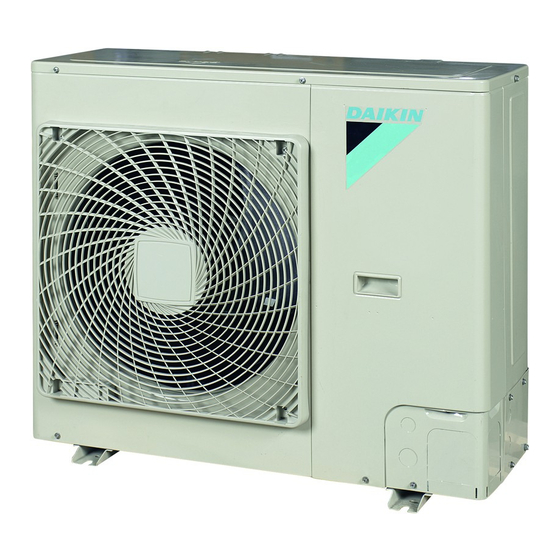
- Page 1 INSTALLATION MANUAL Split System air conditioners REQ71B8V3B REQ71B2V3B REQ100B8V3B REQ71B8W1B REQ71B2W1B REQ100B8W1B REQ125B8W1B...
- Page 2 B 2 B 2 D 2 D 2 D 2 D 2 L 1 L 1 B 1 B 1 L 2 L 2 D 1 D 1 (1000) B 2 B 2 D 2 D 2 D 2 D 2 (1500) L 1 L 1 B 1 B 1...
- Page 3 3PW25005-8D...
-
Page 4: Table Of Contents
Improper installation work may result in accidents due to falling OTHER DAMAGE TO THE EQUIPMENT. BE SURE ONLY of equipment. TO USE ACCESSORIES MADE BY DAIKIN WHICH ARE SPECIFICALLY DESIGNED FOR USE WITH THE Make certain that all electrical work is carried out by qualified... -
Page 5: Before Installation
EFORE INSTALLATION Caution Ground the air conditioner. Since design pressure is 4.15 MPa or 41.5 bar, pipes of Grounding resistance should according national larger wall thickness may be required. Refer to "Selection regulations of piping material" on page 4 Do not connect the earth wire to gas or water pipes, lightning conductor or telephone earth wire. -
Page 6: Selecting Installation Site
If you install the unit on a frame, please install a waterproof plate ELECTING INSTALLATION SITE within 150 mm of the underside of the unit in order to prevent the invasion of water from the lower direction. Make sure to provide for adequate measures in order When installing the unit in a place frequently exposed to snow, to prevent that the outdoor unit be used as a shelter pay special attention to the following:... -
Page 7: Installation Servicing Space
In case of installing multiple units (2 units or more) in lateral NSTALLATION SERVICING SPACE connection per row. The numerical figures used in here represent the dimensions for the 71-100-125 class models. Figures between ( ) indicate the dimensions for the 100-125 class models. (Unit: mm) (Refer to "Precautions on installation"... -
Page 8: Precautions On Refrigerant Piping
Refrigerant pipe size Perform a visual check on quality of residual oil in existing refrigerant piping. Pair system (See figure 2) This check is extremely important because using existing piping with deteriorated will cause compressor Refrigerant pipe size breakdown. Gas pipe - Put some residual oil of the pipes you want to reuse on a Class Standard size... - Page 9 Preventing foreign objects from entering Closing the valve Place the hex wrench on the valve bar and turn clockwise. Plug the pipe through-holes with putty or insulating material Stop when the valve bar no longer turns. It is now closed. (procured locally) to close up all gaps, as shown in the figure.
-
Page 10: Evacuating
Cautions for flare connection VACUATING Please refer to the table for the dimensions for processing flares Do not purge the air with refrigerants. Use a vacuum pump to and for the tightening torques. (Too much tightening will end up vacuum the installation. No additional refrigerant is provided for in splitting of the flare.) air purging. -
Page 11: Electrical Wiring Work
Total charging weight of the refrigerant (after a leak, The filled out label must be adhered on the inside of the product and in the proximity of the product charging port (e.g. on the inside of the etc.) service cover). When the entire refrigerant pipe length is within 7.5 meters, charge the refrigerant in accordance with the amount mentioned in the factory refrigerant charge... - Page 12 Model fuse Wire type Size units When cables are routed from the unit, a protection sleeve for the REQ71B8V3B conduits (PG-insertions) can be inserted at the knock-out hole. 32 A (See figure 4) REQ71B2V3B H05VV-U3G Wiring size REQ100B8V3B...
-
Page 13: Test Operation
Therefore the unit starts in cooling mode (even if the (Ω) remote controller is set to heating mode) for about 2-3 minutes and then switches automatically to heating mode. The remote REQ71B8V3B 0.07 controller will always display heating mode. Equipment complying with REQ71B2V3B 0.07... -
Page 14: Wiring Diagram
IRING DIAGRAM : Field wiring : Black : Live : Blue : Neutral : Orange : Terminal : Red : Connector : White : Protective earth (screw) : Yellow : Short circuit connector A1P ......Printed circuit board Q1M,Q2M ....Thermo switch (M1F-M2F) BS1 ...... - Page 15 NOTES NOTES...
- Page 16 4PW23690-1C...
Need help?
Do you have a question about the REQ71B8V3B and is the answer not in the manual?
Questions and answers