Table of Contents
Advertisement
S S
e e
r r
v v
i i
c c
e e
M M
a a
n n
u u
a a
l l
S
e
r
v
i
c
e
M
a
n
u
a
l
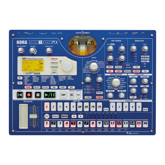
EMX1
CONTENTS
Circuit Diagram: Page 2-10
Block Diagram: Page 11
Structural Diagram: Page 12
Test Mode: Page 13-19
Calibration: Page 20-21
Parts List: Page:22-24
4th Edition
Issued date: July 15, 2004
Issued by: KORG INC.
Advertisement
Table of Contents

Summary of Contents for Korg EMX1
- Page 1 EMX1 CONTENTS Circuit Diagram: Page 2-10 Block Diagram: Page 11 Structural Diagram: Page 12 Test Mode: Page 13-19 Calibration: Page 20-21 Parts List: Page:22-24 4th Edition Issued date: July 15, 2004 Issued by: KORG INC.
- Page 13 EMX-1 Test Mode How to start and operate the test mode: ERASE + PATTERN & POWER ON: Internal test, ERASE + STEP EDIT & POWER ON: Adjustment of valve circuit, L/R balance calibration, Tube gain balance measurement SHIFT + DRUM PART 1 & POWER ON: Internal skip SHIFT + DRUM PART 3 &...
- Page 14 EMX-1 Valve & L/R Balance Adjust Cable White White 2.2M Ω Metal Film Resistor...
- Page 15 Test Mode 1 (Internal test). After replacing the main board, please take the following procedures firstly. Connect the audio cable as follows:...
- Page 16 [MIC/LINE] : LINE [EFFECT] : REVERB [SYNTH OSCILLATOR] : AUDIO IN + COMB 3. Insert the SmartMedia, which is supplied by Korg. 4. Press [ERASE] + [PATTERN] + [STANDBY] (POWER ON) 5. Executing Internal Device check start..If the internal checking works correctly, it proceeds to the next steps automatically.
- Page 17 6-4. A/D check <#ADC> Rotate the knobs to "MIN --> MAX --> MIN". NOTE: As for the knobs with (c) as below, rotate the knob to the center position and proceed to the next knob. "MIN --> MAX --> MIN --> CENTER". [PITCH/GLIDE(c)] ->...
- Page 18 2. Connect the stereo plug of the cable to PHONES and the monaural plug to AUDIO IN. 2. Insert the SmartMedia, which is supplied by Korg. 3. Turn the power on while pressing [ERASE] + [PART EDIT]. 1. "<NAND> Fmt OK"...
- Page 19 7."<NAND> UserLd" 8. "<NAND> Chking" NOTE: If the step stops any of the above indications in the display, press [SHIFT]+[15]. If the system data is loaded correctly, "Valv Wup ***sec"(000-160sec) is indicated in the display. If any other message is displayed such as "@@@@@ x:$$$", it might be an error.
- Page 20 EMX-1/ESX-1 Tube Calibration Connect the stereo plug of the cable (see fig.) to PHONES and the monaural plug to INPUT. 2. While pressing ERACE and STEP EDIT, turn the power on. “Valv Wup” is indicated as stand-by for pre-heating, and also the waiting time is indicated. Set up the volume knob and switches as follows: MASTER VOLUME : MAX TUBE GAIN...
- Page 21 4. As well as Ajst(L)”, “Ajst (R)” and a 4 digits figure are indicated in the LCD. If the value is leas than 0010, the test is O.K.. Press the 16 knob at the right bottom. If the value is over it, it is required to adjust the valve. Adjust the variable resistors which correspond to the channels referring to the photo above.
- Page 22 PART CODE PART NAME NOTE Q'TY 001236600 PCB ASSY KLM-2366 EMX-1 M.PART 001236700 PCB ASSY KLM-2367 EMX-1 M.PART 001236900 PCB ASSY KLM-2369 EMX-1 M.PART 001244400 PCB ASSY KLM-2444/45 EMX-1 M.PART 304000070 TR 2SA812-T1B (M5-7) (TS) KLM-2369 304000070 TR 2SA812-T1B (M5-7) (TS) KLM-2366 304010020...
- Page 23 PART CODE PART NAME NOTE Q'TY 404001070 CHIP INDUCTOR BLM11B102SPT:TS KLM-2366 415004500 TOUCH SHEET FS-MR048-08 10KS M.PART 454012707 DIN SOCKET DJ-004-C KLM-2366 454012709 DIN SOCKET DS-05-02(W/OUT SW) KLM-2366 474029500 SM CONNECTOR CN015R-3013-0 KLM-2366 620018200 POWER SW KNOB KOC-E40224 M.PART 644003000 X-507 GND SPRING KOC-C46014 M.PART...
- Page 24 PART CODE PART NAME NOTE Q'TY *471X120001 PIN HEADER JS-1125-10 KLM-2366 *471X120002 PIN HEADER JS-1125-15 KLM-2366 *471X120003 FLAT CABLE CONNECTOR BA-40R KLM-2366 *471X120004 PIN HEADER JS-1125-6 KLM-2369 *471X120005 PIN HEADER JS-1125-8 KLM-2369 *471X120006 PIN HEADER JS-1125-12 KLM-2369 *471X120007 PIN HEADER JS-1125-7 KLM-2369 *471X120008 FPC CONNECTOR 5597-05APB KLM-2444/45...


Need help?
Do you have a question about the EMX1 and is the answer not in the manual?
Questions and answers