Table of Contents
Advertisement
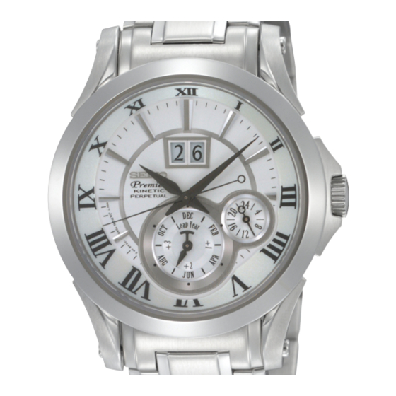
Parts List/ TECHNICAL GUIDE
Item
• 3 hands (Hour/Minute/Second )
• Big calendar (Date)
• Year /Month indicator
• 24 hour indicator
Driving system
Additional function
Normal position
Crown operation
1st click position
2nd click position
Loss/Gain
Regulation system
Gate time for rate measurement
Current consumption
Coil resistance
Power generator
Rechargeable
Power supply
Duration of charge
Number of jewels
KINETIC Cal. 7D56A
Cal. No.
Stepping motor 2 pieces and 1 piezoelectric motor for calendar
• Perpetual calendar function up to 28 Feb 2100
• Power save function
• Time relay function
• Energy depletion forewarning function
• Overcharge prevention function
• Electronic circuit reset function
• Date correction function
• Second hand stop function
Free
Calendar setting
Time setting
Monthly rate: less than 15 seconds (worn on the wrist at temperature
range between 5 ºC and 35 ºC)
Nil
Use 10-second gate
Movement:
Circuit block:
Circuit block for calendar: less than 0.40 µA
Second coil block:
Hour and minute coil block:
Generating coil block:
Automatic generating system
MT920 Manganese titanium lithium rechargeable battery
battery
Operating
0.45V - 2.50V
voltage range
Validity of time relay function: approximately 4 years (from full charge)
16 jewels
Movement
• Diameter
Outside : Ø 32.0 mm Casing : Ø 30.0 mm
• Height: 6.10 mm
less than 0.70 µA
less than 0.40 µA
Coil for driving hands:
Coil for detecting generation: 270Ω - 330 KΩ
1/44
7D56A
2.00 - 2.45 KΩ
1.00 KΩ - 1.25 KΩ
360 - 420Ω
Advertisement
Table of Contents

Related Manuals for Seiko 7D56A


Summary of Contents for Seiko 7D56A
- Page 1 PARTS LIST/ TECHNICAL GUIDE KINETIC Cal. 7D56A [SPECIFICATIONS] Cal. No. 7D56A Item Movement • 3 hands (Hour/Minute/Second ) • Diameter • Big calendar (Date) Outside : Ø 32.0 mm Casing : Ø 30.0 mm • Year /Month indicator • Height: 6.10 mm •...
- Page 2 Cal. 7D56A FEATURES SEIKO Kinetic Perpetual Cal. 7D56 is developed based on the design of SEIKO Kinetic Auto Relay Cal. 5J series with a newly designed perpetual calendar mechanism featuring a unique big date display. Although Cal.7D series features new functions, the experience of repairing the existing KINETIC series watches will be helpful.
- Page 3 SPECIFICATIONS Cal. 7D56A Year indicator CAL. 7D56 L.Y. Year Indication Number of the years Leap Year Three Years passed since One year Two Years the last leap year 2009 2011 2008 2010 Year 2013 2015 2012 2014 2093 2095 2092 2094 2097 2099 2096 2098 * The design of the year indicator may vary depending on the model. HOW TO CHARGE THE WATCH 1.
- Page 4 SPECIFICATIONS Cal. 7D56A HOW TO SET THE PERPETUAL CALENDAR Date, month and year are interlocked on the perpetual calendar. To set the month or year, ● advance the date by turning the crown until the month or year becomes adjustable.
- Page 5 PARTS LIST Cal. 7D56A [AUTOMATIC GENERATING MECHANISM] CASEBACK OSCILLATING WEIGHT SCREW 0022 490 OSCILLATING WEIGHT 0500 531 OSCILLATING WEIGHT WHEEL 1002 504 RECHARGEABLE BATTERY CLAMP SCREW 0012 354 RECHARGEABLE Remarks on removing the winding stem BATTERY CLAMP To remove the winding stem when taking out the...
- Page 6 PARTS LIST Cal. 7D56A [CALENDAR UNIT (1)] DATE DISK HOLDER 0839 506 DATE DISK FOR TEN’S DIGIT DATE DISK FOR UNIT’S DIGIT DATE JUMPER FOR UNIT’S DIGIT 1024 500 YEAR INDICATOR 1.Positioning pin A for spring DRIVING WHEEL for intermediate wheel...
- Page 7 PARTS LIST Cal. 7D56A [CALENDAR UNIT (2)] MONTH INDICATOR WHEEL 1021 506 DETECTION WHEEL FOR MONTH INDICATOR 1002 510 INTERMEDIATE YEAR INDICATOR WHEEL 0817 516 DETECTION WHEEL FOR YEAR INDICATOR 1002 511 YEAR INDICATOR DRIVING WHEEL 0802 512 YEAR INDICATOR WHEEL...
- Page 8 PARTS LIST Cal. 7D56A [CALENDAR UNIT (3)] 29 1ST INTERMEDIATE DATE WHEEL 0817 512 30 PIEZOELECTRIC ROTOR BLOCK 4146 514 31 INSULATOR FOR PIEZOELECTRIC MOTOR 4216 540 32 PIEZOELECTRIC MOTOR CONDUCTIVE PLATE 0105 502 33 PIEZOELECTRIC STATOR BLOCK 4583 500...
- Page 9 PARTS LIST Cal. 7D56A [CALENDAR UNIT (4)] 37 CALENDAR PLATE 4408 563 DATE DRIVING WHEEL FOR TEN'S DIGIT 0802 506 DATE PINION FOR TEN'S DIGIT 40 CALENDAR CORRECTOR 1013 504 3RD INTERMEDIATE WHEEL 41 CALENDAR CORRECTOR 0962 501 4TH INTERMEDIATE...
- Page 10 PARTS LIST Cal. 7D56A [CIRCUIT BLOCK] SCREW FOR CIRCUIT BLOCK COVER A 0012 354 CIRCUIT BLOCK COVER A 4457 505 CIRCUIT BLOCK COVER D 4457 774 SCREW FOR CIRCUIT BLOCK COVER C 0012 354 CIRCUIT BLOCK COVER C 4457 966 OSCILLATING WEIGHT BRIDGE...
- Page 11 PARTS LIST Cal. 7D56A [MOTORS/GEAR TRAIN MECHANISM/SETTING MECHANISM (1)] 59 INSULATOR FOR CIRCUIT BLOCK 4216 538 60 GENERATING COIL BLOCK 4002 525 62 HOUR AND MINUTE 61 SECONDS COIL BLOCK COIL BLOCK 4002 524 4002 530 TRAIN WHEEL BRIDGE SCREW...
- Page 12 PARTS LIST Cal. 7D56A [SETTING MECHANISM (2)] YOKE 0384 557 TRAIN WHEEL SETTING LEVER 0391 557 SETTING STEM CLUTCH WHEEL 0282 523 CALENDAR CORRECTOR 1ST INTERMEDIATE WHEEL 0962 557 85 RECHARGEABLE BATTERY CONNECTION(+) 4271 522 GENERATING STATOR 4239 527 SECONDS STATOR...
- Page 13 How to find the correct parts, if not determined by 4 digit caliber number Following parts are determined based on the design of watches, such as hands height, dial color, and design of cases. Please refer to the SEIKO WATCH PARTS CATALOGUE in order to choose corresponding parts.
- Page 14 Tools and consumables required for disassembling/reassembling • Movement holder Universal movement holder (S-682) • Watch oils SEIKO watch grease (S-6) and watch oils (AO-3 and AO-2) AO-3 AO-2 The Cal. 7D series requires a precise alignment of its calendar train wheels, jumpers and springs.
- Page 15 TECHNICAL GUIDE Cal. 7D56A REMARkS ON DiSSASEMbLiNG AND REASSEMbLiNG THE MOvEMENT l How to remove the SETTING STEM before dismantling the movement Crown position: 1st CLICK POSITION Push the SETTING LEVER gently (refer to the picture on Push here. the right) in order to disengage it from the SETTING STEM.
- Page 16 TECHNICAL GUIDE Cal. 7D56A l Setting mechanism SETTING LEVER “A” portion YOKE TRAIN WHEEL SETTING LEVER YOKE • Make sure that the spring portion of the YOKE (“A” in the illustration) makes secure contact with the pin. Note: If a defective contact occurs between...
- Page 17 TECHNICAL GUIDE Cal. 7D56A l Gear train mechanism 43 CENTER WHEEL BRIDGE • Setting position See the illustration at right. • How to install “A” and “B” portions have elasticity and are made tight for the guide tubes to which they are set.
- Page 18 TECHNICAL GUIDE Cal. 7D56A For the discrimination and setting position of the parts, refer to the table below. 70 SECONDS ROTOR 71 HOUR AND MINUTE ROTOR 67 FOURTH WHEEL 68 THIRD WHEEL Thickness of the pinion Notes * Take care not to mistake the...
- Page 19 TECHNICAL GUIDE Cal. 7D56A Notes: SECONDS INTERMEDIATE SECONDS WHEEL * Lubricate the MINUTE WHEEL before reassembling ROTOR SECONDS WHEEL it to the TRAIN WHEEL BRIDGE. When lubricating it, take care not to stain the pinion with oil. * Do not lubricate the lower pivots of the THIRD WHEEL and INTERMEDIATE SECONDS WHEEL excessively.
- Page 20 TECHNICAL GUIDE Cal. 7D56A 1 OSCILLATING WEIGHT SCREW OSCILLATING WEIGHT SCREW · Before tightening the OSCILLATING WEIGHT SCREW, check that the gear of the OSCILLATING WEIGHT WHEEL securely engages with the pinion of the INTERMEDIATE WHEEL FOR GENERATING ROTOR (“A”portion in the illustration).
- Page 21 7 D 5 6 A T e c h n i c a l G u i d e No. 1 PROCESS ILLUSTRATION AND SPECIAL INSTRUCTIONS [CALENDAR CIRCUIT BLOCK PIEZOELECTRI <48> Set the PIEZOELECTRIC <49> Set the CONTROL WHEEL MOTOR] Set the MOTOR SETTING LEVER.
- Page 22 7 D 5 6 A T e c h n i c a l G u i d e No. 2 PROCESS ILLUSTRATION AND SPECIAL INSTRUCTIONS Lubricate 1 to 5 as illustrated. Lubrication Lower pivots GENERATING ROTOR Lubricate 1 to 5 as illustrated.
- Page 23 7 D 5 6 A T e c h n i c a l G u i d e No. 3 PROCESS ILLUSTRATION AND SPECIAL INSTRUCTIONS Assemble the CIRCUIT BLOCK <45> Assemble the CIRCUIT BLOCK <38> Assemble the DATE DRIVING FOR CALENDAR.
- Page 24 7 D 5 6 A T e c h n i c a l G u i d e No. 4 PROCESS ILLUSTRATION AND SPECIAL INSTRUCTIONS Assemble the <37> Assemble the CALENDAR CALENDAR PLATE PLATE Make sure that the three posts are Lubricate the upper securely engaged (see illustration).
- Page 25 7 D 5 6 A T e c h n i c a l G u i d e No. 5 PROCESS ILLUSTRATION AND SPECIAL INSTRUCTIONS <36> Set the DATE JUMPER FOR TEN’S Set the DATE <34> Set the MONTH DIGIT and engage it with the PINION FOR JUMPER FOR TEN’S DIGIT.
- Page 26 7 D 5 6 A T e c h n i c a l G u i d e No. 6 PROCESS ILLUSTRATION AND SPECIAL INSTRUCTIONS Set the PIEZOELECTRIC MOTOR SPRING and secure it to the rotor block Assemble PIEZOELECTRIC 1.
- Page 27 7 D 5 6 A T e c h n i c a l G u i d e No. 7 PROCESS ILLUSTRATION AND SPECIAL INSTRUCTIONS Assemble the PIEZOELECTRIC <27> Assemble the PIEZOELECTRIC MOTOR MOTOR COVER. COVER. Tighten the Insert the “a” portion of the cover to the slot PIEZOELECTRIC of the plate and make sure that the pivot of MOTOR COVER...
- Page 28 7 D 5 6 A T e c h n i c a l G u i d e N0. 8 PROCESS ILLUSTRATION AND SPECIAL INSTRUCTIONS <24> Assemble the CALENDAR Assemble the INTERMEDIATE MONTH INDICATOR WHEEL. CONTROL WHEEL and secure the jumper [ CALENDAR TRAIN to it.
- Page 29 7 D 5 6 A T e c h n i c a l G u i d e No. 9 ILLUSTRATIONS AND SPECIAL INSTRUCTIONS PROCESS <20> Assemble the YEAR INDICATOR Set the POSITIOINING PIN B Set the DRIVING WHEEL. POSITIONING PIN Supporting pin Set the pin to the hole next...
- Page 30 7 D 5 6 A T e c h n i c a l G u i d e No. 10 ILLUSTRATIONS AND SPECIAL INSTRUCTIONS PROCESS Check the alignments of <14> Assemble the CALENDAR <11> Set the DATE JUMPER FOR wheels before TRAIN BRIDGE.
- Page 31 7 D 5 6 A T e c h n i c a l G u i d e No. 11 ILLUSTRATIONS AND SPECIAL INSTRUCTIONS PROCESS Assemble the DATE <9> Assemble the DATE DISK FOR TEN`S DIGIT. <10> Assemble the DATE DISK FOR UNIT’S DISK FOR UNITʻ...
- Page 32 Technical guide Cal. 7D56A REMARKS ON DECASING/CASING, DIAL AND HANDS SETTING l How to install the hands Cal. 7D56 features the perpetual calendar. Thus, the hands should be carefully mounted exactly as instructed below. Pull out the SETTING STEM to the first click position, and set the calendar to “ the leap year, January 1.”...
- Page 33 Technical guide Cal. 7D56A • Set the movement. Check the positions of date, month and year. (Ensure it is set to a leap year, January 1) Date The date should be positioned as shown in the illustration. Month The hole of the detection...
- Page 34 BLOCK COVER A. CIRCUIT BLOCK COVER A * When measuring the current consumption using the SEIKO digital multi-tester (S-860), use the range of 40 μ A of SUPPLY V (= 1.55 V) & GATE TIME (2 S) 3. Swing the OSCILLATING WEIGHT as...
- Page 35 CUIT BLOCK (please refer to “ Structure of the circuit block” below).” * When measuring the current consumption using the SEIKO digital multi-tester (S-860), use the range of 40 μ A of SUPPLY V (= 1.55 V) & GATE TIME (2 S) 2.
- Page 36 Technical guide Cal. 7D56A l Coil block resistance 61 Seconds coil block: 2.00kΩ -– 2.45kΩ 62 Hour and minute coil block: Coil for driving hands: 1.00 kΩ -– 1.25 kΩ Coil for detecting generation: 270 Ω-– 330 Ω 60 Generating coil block: 360Ω...
- Page 37 Technical guide Cal. 7D56A l Checking the automatic generating system 1. Apply the (-) probe of the tester to the (-) terminal of the battery and (+) probe to the CIRCUIT BLOCK COVER (A). Then, measure the voltage of the RECHARGEABLE BAT- TERY.
- Page 38 Technical guide Cal. 7D56A l Function check Operation Function Checkpoint Pull out the crown to the 2nd Make sure that it has click and push it Setting mechanism - a click at each back in to the switching the position and the normal ...
- Page 39 Cal. 7D56A l Inspection of perpetual calendar and PTP operation in move state Cal. 7D56A is equipped with a perpetual calendar which automatically advances the calendar up to February 28, 2100. Here, an inspection is carried out if the “perpetual calendar” normally operates.
- Page 40 Technical guide Cal. 7D56A Inspection method of perpetual calendar With the back case temporarily closed, recharge the watch until the amount of stored electrical energy in the rechargeable battery reaches above 1.3v. 2. Pull out the crown from the “0” position to the first click position, and leave it as it is for two sec- onds or longer.
- Page 41 Technical guide Cal. 7D56A l Water resistance test Check the water resistance according to the designated specification of the watch. Marking on the case back Test method Applied pressure WATER RESISTANT (WATER RESIST) 3 BAR Air leak test WATER RESIST 5BAR...
- Page 42 Technical guide Cal. 7D56A TROUBLESHOOTING l The following are the tips on repairing Cal. 7D56A, which you will find helpful in working on the watch. ● 1. Summary of important functions characteristic of Cal. 7D56A 1) The power save function is activated after the watch is left untouched for approximately 24 hours.
- Page 43 Technical guide Cal. 7D56A Problems, causes and methods of repair Problems Possible causes Methods of repair and checking The quickness of the hand 1) The coil for detecting 1) Check the resistance of the coil movement after the activation generation of the hour and for detecting generation.
- Page 44 Technical guide Cal. 7D56A Problems Possible causes Methods of repair and checking The current consumption for 1) The light from outside the 1) Shut out the light, and make the the circuit block alone exceeds movement is affecting the measurement again.
Need help?
Do you have a question about the 7D56A and is the answer not in the manual?
Questions and answers