Table of Contents
Advertisement
Quick Links
Advertisement
Table of Contents

Related Manuals for Idis DR-2204P


Summary of Contents for Idis DR-2204P
- Page 1 Network Video Recorder Installation Manual DR-2204P DR-2208P DR-2216P Powered by...
-
Page 2: Safety Precautions
Before reading this manual This manual contains basic instructions on installing and using DirectIP™ Network Video Recorder, an IDIS product. Users who are using this product for the first time, as well as users with experience using comparable products, must read this manual carefully before use and heed to the warnings and precautions contained herein while using the product. -
Page 3: Important Safeguards
Before reading this manual Important Safeguards 1. Read Instructions 14. Damage requiring Service All the safety and operating instructions should be read before the appliance Unplug this equipment from the wall outlet and refer servicing to qualified is operated. service personnel under the following conditions: 2. -
Page 4: Fcc Compliance Statement
Before reading this manual In-Text Symbol Type Description Caution Important information concerning a specific function. Note Useful information concerning a specific function. User’s Caution Statement Caution: Any changes or modifications to the equipment not expressly approved by the party responsible for compliance could void your authority to operate the equipment. - Page 5 IDIS Co., Ltd. reserves all rights concerning this manual. Use or duplication of this manual in part or whole without the prior consent of IDIS Co., Ltd. is strictly prohibited. Contents of this manual are subject to change without prior notice.
-
Page 6: Table Of Contents
Table of Contents Part 1 – Introduction ......... 7 Product Features . -
Page 7: Part 1 - Introduction
Part 1 – Introduction Product Features This is a DirectIP™-enabled video recorder that supports surveillance, recording, and playback of video from network cameras (or video encoders). This NVR (Network Video Recorder) unit offers the following features: • Real-time 4/8/16-channel DirectIP™ network surveillance •... -
Page 8: Accessories
Upon unpackaging the product, check the contents inside to ensure that all the following accessories are included. Network Video Recorder Power Cable / DC Adapter(12V, 48V) Quick Guide Manual and IDIS Center Program CD Optical USB Mouse IR Remote Control Assembly Screws for Adding Hard... -
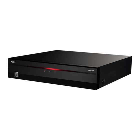
Page 9: Overview
Part 1 – Introduction Overview Front Panel USB Ports LEDs • Remote control sensor is located on the bottom center of the front panel. Ensure that the sensor remains unobstructed at all times. If obstructed, the sensor might not be able to receive remote control signals. •... - Page 10 Part 1 – Introduction 2 LEDs • Power LED: Lights up while the main unit is in operation. HDD LED: Flashes when data is being written on the HDD or a video search is in progress. • Network LED: Flashes when the main unit is linked to an ethernet. •...
-
Page 11: Rear Panel
Part 1 – Introduction Rear Panel Factory Reset Button Audio Ports VGA Out Port HDMI Out Port eSATA Port Video In / PoE Ports Network Port Video In / Ext. Port Alarm Connection Ports RS-232 Port Power In Port (12V) Power In Port (48V) -
Page 12: Rear Panel Connections
Part 1 – Introduction Rear Panel Connections Video Connection • Video In/PoE Port Monitor Connection Connect to the VGA OUT or HDMI port. Connect network cameras or video encoders to the NVR using RJ-45 cable (Cat5, Cat5e, or Cat6). The NVR recognizes DirectIP™... -
Page 13: Network Connection
Part 1 – Introduction eSATA Connection Alarm Connection Connect external hard drives to these ports. Connect alarm connectors to these ports. Do not connect or disconnect an eSATA device while the NVR is powered on. To connect an eSATA device, first turn off the NVR and unplug the power cable. - Page 14 Part 1 – Introduction • NO (Relay Alarm Outputs) • Organize the power cable so that it will not cause people to trip over or become damaged from chairs, This NVR is capable of activating/deactivating buzzers, cabinets, desks, and other objects in the vicinity. Do lights, and other external devices.
- Page 15 Part 1 – Introduction Connections on the Rear Panel eSATA Storage Device Speaker VGA Monitor Camera DirectIP™ Gigabit PoE Switch HDMI Monitor Camera Alarm Network Sensor IDIS Center Power (48V) Remote Monitoring Power (12V) Keyboard...
-
Page 16: Remote Control
Part 1 – Introduction Remote Control ID Button PANIC Button Camera Buttons STATUS Button LAYOUT Button PTZ Control Buttons REGISTER MODE Button THUMBNAIL Button CALENDAR Button KEYLOCK Button SETUP Button FREEZE Button LOG Button Enter Button Arrow Buttons ALARM Button SEQUENCE Button &... - Page 17 Part 1 – Introduction 1 ID Button 7 REGISTER MODE Button Used to assign remote control ID values. Used in Live mode to access Camera Registration mode. No additional remote control assignment is necessary if the system's ID is 0. If the system's ID is 8 THUMBNAIL Button a number between 1 and 9, however, you will need Used in Playback mode to access Thumbnail Search...
- Page 18 Part 1 – Introduction $ Enter Button b MENU Button Pressing the MENU button while in Live mode Used to make menu option selections and register data entries. In addition, pressing this button while displays the Live menu. Alternatively, pressing the a camera screen is selected by pressing the Menu button while in Time-lapse Search mode displays the button in Live or Playback mode displays the Camera...
-
Page 19: Part 2 - Appendix
Part 2 - Appendix System Log Types Boot Up Panic On System Shutdown Panic Off Restart Clear All Data Upgrade Success Clear Disk Upgrade Error Format Disk Power Failure Disk Full Time Changed Auto Deletion Time Zone Change Search Begin Time Sync. -
Page 20: Error Code Types
Part 2 - Appendix Error Code Types Upgrade Error Codes Type Type Unknown Error Remote Network Error Incorrect File Version No Remote Upgrade Permission Incorrect OS Version Remote Upgrade File Save Failure Incorrect Software Version Remote Upgrade Cancelled by User Incorrect Kernel Version USB Storage Device Mount Failure Storage Device Mount Failure... - Page 21 Part 2 - Appendix Clip Copy Error Codes Type Type Unknown Error Disk Error Device Error Clip Player Execution File Not Found Device Connection Failure Clip Player Execution File Access Failure CD Media Not Found Clip Player Execution File Save Failure Incorrect Media Image Generation Failure File Name Taken...
- Page 22 Part 2 - Appendix Network Error Codes Type Type Cause of Failure Unknown Connection Cancelled by User Normal Logout No Response from Network Device Host All Channels in Use - Connection Denied High Network Noise Level Incorrect Product Version Info Transmission Queue Full Incorrect User Name or Password Incorrect OEM Info...
-
Page 23: Troubleshooting
Part 2 - Appendix Troubleshooting Problem Solution • Check the power cable connection status. The main unit won't turn on. • Check the power outlet. • Check the camera's video cable connection status. • Check the monitor's video cable connection status. Unable to display Live video. -
Page 24: Specifications
1920 x 1200, 1920 x 1080, 1680 x 1050, 1600 x 1200 Up to 480ips @ Full HD (DR-2216P) Recording Speed (IPS) Up to 240ips @ Full HD (DR-2208P) Up to 120ips @ Full HD (DR-2204P) Playback Speed (IPS) 120ips @ Full HD... - Page 25 Network Audio In Audio Out 1 line Audio Out, RCA Text In POS Interface, ATM Interface Connectors Video In Ethernet: 4/9/9 ports (DR-2204P/2208P/2216P) Camera Power Out Ethernet: 4/8/8 ports (DR-2204P/2208P/2216P) HDMI: 1 HDMI Monitor Out VGA: 1 DB15 Audio Out...
- Page 26 Storage Part 2 - Appendix Internal Storage 2 SATA2 bays External Storage eSATA 1 port Clip Copy Device USB Storage Device (USB HDD, USB Memory, etc.) Some hard disks may not function properly when mounted on to this product. Refer to the compatibility chart below before mounting any additional hard disk on to the product.
- Page 27 IDIS Co., Ltd. For more information, please visit at www.idisglobal.com...
Need help?
Do you have a question about the DR-2204P and is the answer not in the manual?
Questions and answers