Table of Contents
Advertisement
Quick Links
Advertisement
Table of Contents

Related Manuals for thomann PAR 36


Summary of Contents for thomann PAR 36
- Page 1 PAR 36 PAR 56 PAR 64 LED PAR user manual...
- Page 2 Musikhaus Thomann e.K. Treppendorf 30 96138 Burgebrach Germany Telephone: +49 (0) 9546 9223-0 E-mail: info@thomann.de Internet: www.thomann.de 30.10.2014, ID: 193245, ... (V2)
-
Page 3: Table Of Contents
Installation..............................15 Setup................................19 Connections and controls........................21 Operation..............................23 7.1 Starting up the device........................23 7.2 ‘Auto change’ mode........................23 7.3 ‘Auto fade’ mode..........................24 7.4 Manual mode............................. 25 7.5 DMX mode............................26 PAR 36 PAR 56 PAR 64... - Page 4 Table of contents Technical specifications........................28 Plug and connection assignments....................33 Troubleshooting............................34 Cleaning............................... 36 Protecting the environment......................37 LED PAR...
-
Page 5: General Notes
If you sell the unit please make sure that the buyer also receives this manual. Our products are subject to a process of continuous development. Thus, they are subject to change. PAR 36 PAR 56 PAR 64... -
Page 6: Further Information
General notes 1.1 Further information On our website (www.thomann.de) you will find lots of further information and details on the following points: Download This manual is also available as PDF file for you to download. Use the search function in the electronic version to find the topics of Keyword search interest for you quickly. -
Page 7: Notational Conventions
Texts and values displayed on the device are marked by quotation marks and italics. Examples: ‘24ch’ , ‘OFF’ . 1.3 Symbols and signal words In this section you will find an overview of the meaning of symbols and signal words that are used in this manual. PAR 36 PAR 56 PAR 64... - Page 8 General notes Signal word Meaning DANGER! This combination of symbol and signal word indicates an immediate dangerous situation that will result in death or serious injury if it is not avoided. WARNING! This combination of symbol and signal word indicates a pos‐ sible dangerous situation that can result in death or serious injury if it is not avoided.
- Page 9 General notes Warning signs Type of danger Warning – danger zone. PAR 36 PAR 56 PAR 64...
-
Page 10: Safety Instructions
Safety instructions Safety instructions Intended use This device is intended to be used as an electronic illumination effect using LED technics. Use the device only as described in this user manual. Any other use or use under other operating conditions is considered to be improper and may result in personal injury or property damage. No liability will be assumed for damages resulting from improper use. - Page 11 Electric shock caused by short-circuit Do not modify the mains cable or the plug. Failure to do so could result in electric shock/death or fire. If in doubt, seek advice from a registered electrician. PAR 36 PAR 56 PAR 64...
- Page 12 Safety instructions WARNING! Eye damage caused by high light intensity Never look directly into the light source. WARNING! Risk of epileptic shock Strobe lighting can trigger seizures in photosensitive epilepsy. Sensitive persons should avoid looking at strobe lights. NOTICE! Risk of fire Do not cover the device nor any ventilation slots.
- Page 13 Failure to do so could result in damage to the device and possibly injure the user. Unplug the device before electrical storms occur and when it is unused for long periods of time to reduce the risk of electric shock or fire. PAR 36 PAR 56 PAR 64...
-
Page 14: Features
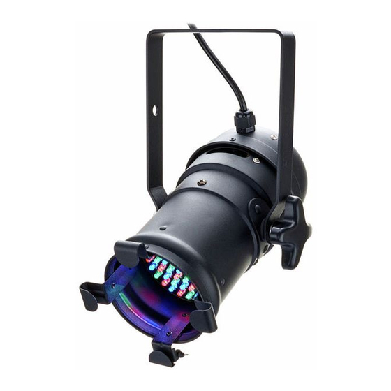
Features Features The LED PAR is particularly suitable for professional lighting applications, e.g. at events, on rock stages, in theatres and musicals or TV productions. It is characterized by a low power con‐ sumption and long life span. Special features of this device: LEDs in three primary colours (RGB) Control via DMX or DIP switches on the unit Preprogrammed automatic shows... -
Page 15: Installation
Make sure that the installation complies with the standards and rules that apply in your country. Always secure the device with a secondary safety attachment, such as a safety cable or a safety chain. PAR 36 PAR 56 PAR 64... - Page 16 Installation NOTICE! Risk of overheating Always ensure sufficient ventilation. The ambient temperature must always be below 40 °C (104 °F). NOTICE! Use of stands When mounting the device onto a stand, ensure that the stand is in a safe and stable position and that the weight of the device does not exceed the maximum permissible load capacity of the stand.
- Page 17 Work from a stable platform whenever you install or move the device or when you perform any kind of maintenance. Block access under the work area. The safety cable must be attached to the bracket. PAR 36 PAR 56 PAR 64...
- Page 18 Installation Please note that this device must not be connected to a dimmer. LED PAR...
-
Page 19: Setup
Setup Setup Establish all connections as long as the unit is switched off. Use the shortest possible high- quality cables for all connections. PAR 36 PAR 56 PAR 64... - Page 20 Setup Connections in DMX mode Connect the DMX input of the device to the DMX output of a DMX controller or another DMX device. Connect the output of the first DMX device to the input of the second one, and so on to form a daisy chain.
-
Page 21: Connections And Controls
Connections and controls Connections and controls Rear panel PAR 36 PAR 56 PAR 64... - Page 22 Connections and controls 1 Power cord. 2 Bracket for floor placement or hanging. 3 Locking screws for the mounting bracket. 4 [DMX IN] DMX input. 5 [DMX OUT] DMX output. 6 [SPEED] For manual speed setting. 7 DIP switches for setting different functions depending on the mode. 8 [AUTO/MUSIC] Switch for selecting the operating mode (sound control or manual control).
-
Page 23: Operation
Connect the unit to the power grid to start the operation. After a few seconds the unit is ready for use. 7.2 ‘Auto change’ mode Set all DIP switches to ‘OFF’. For sound-control, set the switch to ‘MUSIC’. For controller operation, set the switch to ‘AUTO’. PAR 36 PAR 56 PAR 64... -
Page 24: Auto Fade' Mode
Operation 7.3 ‘Auto fade’ mode Set DIP switch no. 8 to ‘ON’. Set the fade time by adjusting the DIP switches according to the table below to ‘ON’: DIP 1 DIP 2 DIP 3 DIP 4 DIP 5 DIP 6 2,5 s 10 s 20 s... -
Page 25: Manual Mode
Operation 7.4 Manual mode Set DIP switches 7 and 8 to ‘ON’. DIP 1, 2 OFF/OFF ON/OFF OFF/ON ON/ON GREEN DIP 3, 4 BLUE DIP 5, 6 BRIGHTNESS 25 % 50 % 100 % PAR 36 PAR 56 PAR 64... -
Page 26: Dmx Mode
Operation 7.5 DMX mode Set DIP switch 8 to ‘OFF’ and at least one of the other DIP switches to ‘ON’. The channel assign‐ ment is shown in the overview: CH-1 CH-2 CH-3 CH-4 CH-5 MODE GREEN BLUE Speed 0 - 63 = RGB 0 - 255 = DIM 0 - 255 = DIM 0 - 255 = DIM... - Page 27 You can set the DMX channel in a range of 1 to 123 via the DIP switches 1 to 7. DIP switch 1 is the first channel. Configure the desired channel using the DIP switches, whose channel num‐ bers add up then: Channel number PAR 36 PAR 56 PAR 64...
-
Page 28: Technical Specifications
Technical specifications Technical specifications Item no. 193245/193246 Stairville LED PAR 36 Alu black/Alu polished LEDs 61 × high power (21 × red, 19 × green, 21 × blue) Number of DMX channels Operating supply voltage AC 230 V , 50 Hz Power consumption Dimensions (W ×... - Page 29 Number of DMX channels Operating supply voltage AC 230 V , 50 Hz Power consumption 16 W Dimensions (W × D × H) 220 mm × 210 mm × 220 mm Weight 1.4 kg PAR 36 PAR 56 PAR 64...
- Page 30 Technical specifications Item no. 215928/215930 Stairville LED PAR 56 Floor black/polished LEDs 151 × high power (51 × red, 49 × green, 51 × blue) Number of DMX channels Operating supply voltage AC 230 V , 50 Hz Power consumption 16 W Dimensions (W ×...
- Page 31 Number of DMX channels Operating supply voltage AC 230 V , 50 Hz Power consumption 16 W Dimensions (W × D × H) 290 mm × 260 mm × 260 mm Weight 2.12 kg PAR 36 PAR 56 PAR 64...
- Page 32 Technical specifications Item no. 215957/215958 Stairville LED PAR 64 Floor black/polished LEDs 151 × high power (51 × red, 49 × green, 51 × blue) Number of DMX channels Operating supply voltage AC 230 V , 50 Hz Power consumption 16 W Dimensions (W ×...
-
Page 33: Plug And Connection Assignments
The unit offers a 3-pin XLR socket for DMX output and a 3-pin XLR plug for DMX input. Please refer to the drawing and table below for the pin assignment of a suitable XLR plug. Configuration Ground, shielding Signal inverted (DMX–, ‘cold signal’) Signal (DMX+, ‘hot signal’) PAR 36 PAR 56 PAR 64... -
Page 34: Troubleshooting
Troubleshooting Troubleshooting NOTICE! Possible data transmission errors For error-free operation make use of dedicated DMX cables and do not use ordi‐ nary microphone cables. Never connect the DMX input or output to audio devices such as mixers or ampli‐ fiers. In the following we list a few common problems that may occur during operation. - Page 35 DMX interface circuits. If the procedures recommended above do not succeed, please contact our Service Center. You can find the contact information at www.thomann.de. PAR 36 PAR 56 PAR 64...
-
Page 36: Cleaning
Cleaning Cleaning Optical lenses Clean the optical lenses, that are accessible from the outside, regularly in order to optimize the light output. The frequency of cleaning depends on the operating environment: wet, smoky or particularly dirty surroundings can cause more accumulation of dirt on the optics of the device. -
Page 37: Protecting The Environment
Dispose of this device through an approved waste disposal firm or through your local waste facility. When discarding the device, comply with the rules and regulations that apply in your country. If in doubt, consult your local waste disposal facility. PAR 36 PAR 56 PAR 64... - Page 38 Notes LED PAR...
- Page 40 Musikhaus Thomann e.K. · Treppendorf 30 · 96138 Burgebrach · Germany · www.thomann.de...
Need help?
Do you have a question about the PAR 36 and is the answer not in the manual?
Questions and answers