Advertisement
Table of Contents
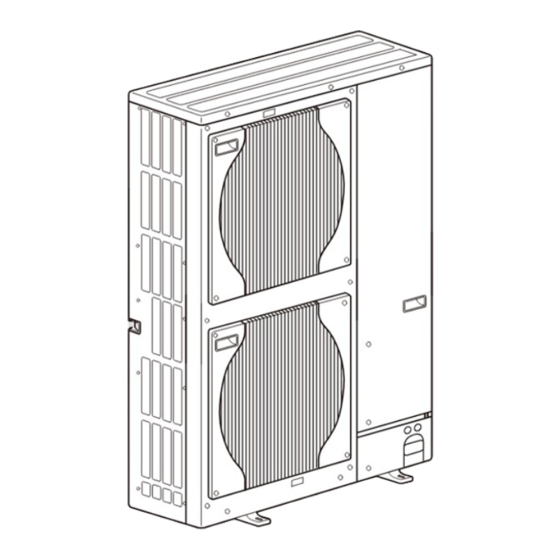
AIR TO WATER HEAT PUMP
SERVICE MANUAL
Outdoor unit
[Model Name]
PUHZ-W112VHA
Salt proof model
PUHZ-W112VHA-BS
[Service Ref.]
PUHZ-W112VHA
PUHZ-W112VHA-BS
R410A
Note:
• This manual describes service
CONTENTS
1. SAFETY PRECAUTION ................................... 2
2. SPECIFICATIONS ............................................ 5
3. DATA ............................................................... 7
4. OUTLINES AND DIMENSIONS ....................... 9
5. WIRING DIAGRAM ........................................ 10
6. WIRING SPECIFICATIONS ............................ 11
7. REFRIGERANT SYSTEM DIAGRAM ............... 12
8. TROUBLESHOOTING ................................... 13
9. DISASSEMBLY PROCEDURE ...................... 41
PARTS CATALOG (OCB562)
June 2014
No. OCH562
data of outdoor unit only.
Advertisement
Table of Contents

Subscribe to Our Youtube Channel
Related Manuals for Mitsubishi PUHZ-W112VHA


Summary of Contents for Mitsubishi PUHZ-W112VHA
-
Page 1: Table Of Contents
AIR TO WATER HEAT PUMP June 2014 No. OCH562 SERVICE MANUAL R410A Outdoor unit [Service Ref.] [Model Name] Note: PUHZ-W112VHA • This manual describes service PUHZ-W112VHA data of outdoor unit only. Salt proof model PUHZ-W112VHA-BS PUHZ-W112VHA-BS CONTENTS 1. SAFETY PRECAUTION ........2 2. -
Page 2: Safety Precaution
SAFETY PRECAUTION 1-1. ALWAYS OBSERVE FOR SAFETY Before obtaining access to terminal, all supply circuits must be disconnected. Preparation before the repair service. • Prepare the proper tools. • Prepare the proper protectors. • Provide adequate ventilation. • After stopping the operation of the air conditioner, turn off the power-supply breaker. •... - Page 3 [1] Cautions for service (1) Perform service after recovering the refrigerant left in the unit completely. (2) Do not release refrigerant in the air. (3) After completing service, charge the cycle with specified amount of refrigerant. [2] Additional refrigerant charge When charging directly from cylinder ·...
- Page 4 1-3. CAUTIONS FOR REFRIGERANT PIPING WORK Tools for R410A (The following table shows whether conventional tools can be used or not.) Tools and materials R410A tools Can R22 tools be used? Can R407C tools be used? Gauge manifold Air purge, refrigerant charge Tool exclusive for R410A and operation check Charge hose...
-
Page 5: Specifications
SPECIFICATIONS 2-1. SPECIFICATIONS PUHZ-W112VHA(-BS) 1φ, 230V, 50Hz Nominal water flow rate (Heating mode) L/min 32.1 Heating(A7/W35) Heating y t i 11.20 ℃ 4.47 (A7/W35) ℃ 2.51 l n i ℃ 11.20 Heating y t i Heating(A2/W35) (A2/W35) 3.34 ℃ 3.35 ℃... - Page 6 2-2. AVAILABLE RANGE (WATER FLOW RATE, RETURN WATER TEMP.) Note: If using the unit out of the available range, the parts of unit might be damaged. <Heating> <Applicable Models> • PUHZ-W112VHA(-BS) 25.0 23.0 Available range 21.0 19.0 17.0 15.0 13.0 11.0...
-
Page 7: Data
DATA 3-1. NOISE CRITERION CURVES PUHZ-W112VHA PUHZ-W112VHA-BS SPL(dB) MODE LINE COOLING HEATING NC-70 NC-60 MICROPHONE NC-50 UNIT NC-40 1.5m NC-30 APPROXIMATE THRESHOLD OF HEARING FOR NC-20 CONTINUOUS NOISE 1000 2000 4000 8000 GROUND BAND CENTER FREQUENCIES, Hz OCH562... - Page 8 3-2. STANDARD OPERATION DATA Mode Cooling (A35/W7) Heating (A7/W35) Capacity 10,000 11,200 Input 3.57 2.51 Outdoor unit PUHZ-W112VHA Phase, Hz 1, 50 Voltage Current 15.8 11.1 Discharge pressure 2.63 2.08 Suction pressure 0.83 0.67 Discharge temperature ºC Condensing temperature ºC Suction temperature ºC...
-
Page 9: Outlines And Dimensions
OUTLINES AND DIMENSIONS PUHZ-W112VHA PUHZ-W112VHA-BS Unit: mm OCH562... -
Page 10: Wiring Diagram
WIRING DIAGRAM PUHZ-W112VHA PUHZ-W112VHA-BS 1 MODEL SELECT SYMBOL NAME SYMBOL NAME The black square ( )indicates a switch position. Terminal Block <Power Supply, Indoor/Outdoor> Connection Terminal < N-Phase > MODEL SW5-6 Motor for Compressor Connection Terminal < Reactor > DCL1, DCL2... -
Page 11: Wiring Specifications
WIRING SPECIFICATIONS FIELD ELECTRICAL WIRING (power wiring specifications) t i n 112V Outdoor unit power supply ~/N (single), 50 Hz, 230 V t i n c r i t i u y t i t i n × Interface unit/Flow temp. controller-Outdoor unit 3 ×... -
Page 12: Refrigerant System Diagram
Refrigerant flow in heating Refrigerant flow in cooling Detail Symbol Part name COMP Compressor DC inverter scroll compressor (Mitsubishi Electric Corporation) H/P SW High pressure switch (63H) For protection (OFF:4.15MPa) L/P SW Low pressure switch (63L) For protection (OFF:-0.03MPa) Plate HEX... -
Page 13: Troubleshooting
TROUBLESHOOTING 8-1. TROUBLESHOOTING <Check code display by self-diagnosis and actions to be taken for service (summary)> Present and past check codes are logged and displayed on the control board of outdoor unit. Actions to be taken for service, which depends on whether or not the trouble is reoccurring at service, are summarized in the table below. Check the contents below before investigating details. - Page 14 8-3. SELF-DIAGNOSIS ACTION TABLE <Abnormalities detected when the power is turned on> Check code Abnormal point and detection method Case Judgment and action 1 No voltage is supplied to terminal 1 Check following items. block (TB1) of outdoor unit. a) Power supply breaker a) Power supply breaker is turned off.
- Page 15 Check code Abnormal point and detection method Case Judgment and action Check disconnection or looseness or polarity Miswiring of Interface unit/Flow temp. Contact failure or miswiring of Interface unit/Flow temp. controller-outdoor controller-outdoor unit connecting wire of Interface unit/Flow temp. unit connecting wire of Interface unit/Flow 1.
- Page 16 <Abnormalities detected while unit is operating> Abnormal point and detection method Judgment and action Check code Case High pressure (High-pressure switch 1 Decreased water flow 1~5 Check water circuit and repair the defect. 63H operated) 2 Clogged filter of water pipe Abnormal if high-pressure switch 63H oper- 3 Dirt of plate heat exchanger ated ( * ) during compressor operation.
- Page 17 Check code Abnormal point and detection method Judgment and action Case 1 Check connection of connector (TH3, TH32, Open/short of outdoor unit thermistors 1 Disconnection or contact failure TH33, TH6/TH7) on the outdoor controller (TH3, TH32, TH33, TH6, TH7, and TH8) of connectors circuit board.
- Page 18 Check code Abnormal point and detection method Judgment and action Case To find out the details about U9 error, turn ON SW2-1, 2-2, 2-3, 2-4, 2-5 and 2-6 when U9 error occurs. Detailed To find out the detail history (latest) about U9 error, turn ON SW2-1, 2-2 and 2-6. codes Refer to "8-7.OUTDOOR UNIT OPERATION MONITOR FUNCTION".
- Page 19 Check code Abnormal point and detection method Judgment and action Case 1 Defective outdoor fan (fan 1 Check outdoor unit air passage. Overheat protection motor) or short cycle of outdoor Abnormal if outdoor pipe thermistor (TH3) unit during cooling operation detects 70: or more or condensing 2 Defective outdoor pipe 23 Turn the power off and on again to check...
- Page 20 Check code Abnormal point and detection method Judgment and action Case Remote controller transmission error Contact failure at transmission Check disconnection or looseness of (E0)/signal receiving error (E4) wire of remote controller Interface unit/Flow temp. controller unit or Abnormal if main or sub remote controller All remote controllers are set transmission wire of remote controller.
- Page 21 Check code Abnormal point and detection method Judgment and action Case Interface unit/Flow temp. controller- 1 Interface unit/Flow temp. 1 Check disconnection or looseness of outdoor unit communication error controller-outdoor unit connecting Interface unit/Flow temp. controller-outdoor wire has contact failure. (Transmitting error) (Outdoor unit) unit connecting wire.
- Page 22 Check code Abnormal point and detection method Judgment and action Case Pipe temperature Abnormal if the following conditions are 1 Leakage or shortage of 1 Check intake superheat. detected for continuously 3 minutes after refrigerant Check leakage of refrigerant. compressor starts operating for 10 minutes. 1.
- Page 23 8-4. HOW TO CHECK THE PARTS PUHZ-W112VHA PUHZ-W112VHA-BS Parts name Check points TH3: Liquid pipe temp. Disconnect the connector then measure the resistance with a tester. TH4: Discharge temp. (At the ambient temperature of 10 to 30:) TH6: Plate Hex liquid pipe temp.
- Page 24 Check method of DC fan motor (fan motor / outdoor controller circuit board) Notes · High voltage is applied to the connector (CNF1, 2) for the fan motor. Pay attention to the service. · Do not pull out the connector (CNF1, 2) of the motor with the power supply on. (It may damage the outdoor controller circuit board and fan motor.) Self check Symptom: The outdoor fan does not run.
- Page 25 8-5. HOW TO CHECK THE COMPONENTS <Thermistor feature chart> Low temperature thermistors • Thermistor <Liquid pipe> (TH3) • Thermistor <Plate Hex liquid pipe> (TH6) • Thermistor <Ambient> (TH7) • Thermistor <Suction pipe> (TH33) Thermistor R0 = 15 kΩ ± 3% B constant = 3480 ±...
- Page 26 Low temperature thermistor • Thermistor <Inlet water> (TH32) Thermistor R0 = 15 kΩ ± 2.5% B constant = 3450 ± 2% =15exp{3450( 273+t – 273 )} 15 kΩ 4.3 kΩ 9.6 kΩ 3.0 kΩ 6.3 kΩ 5.2 kΩ -20 -10 10 20 30 40 50 Temperature(:) <HIGH PRESSURE SENSOR>...
- Page 27 Linear expansion valve (1) Operation summary of the linear expansion valve • Linear expansion valve opens/closes through stepping motor after receiving the pulse signal from the outdoor controller board. • Valve position can be changed in proportion to the number of pulse signal. <Connection between the outdoor controller board and the linear expansion valve>...
- Page 28 (3) How to attach and detach the coil of linear expansion valve <Composition> Linear expansion valve is separable into the main body and the coil as shown in the diagram below. Main body Stopper Coil Lead wire <How to detach the coil> Hold the lower part of the main body (shown as A) firmly so that the main body does not move and detach the coil by pulling it upward.
- Page 29 <CAUTION> TEST POINT 1 is high voltage. 8-6. TEST POINT DIAGRAM Outdoor controller circuit board PUHZ-W112VHA PUHZ-W112VHA-BS Forced defrost, detect Function switch Operation monitor history record reset function Function switch CNDM 1 to 2: Input of low-level sound priority mode...
- Page 30 Outdoor power circuit board Brief Check of POWER MODULE Usually, they are in a state of being short-circuited if they are broken. PUHZ-W112VHA Measure the resistance in the following points (connectors, etc.). PUHZ-W112VHA-BS If they are short-circuited, it means that they are broken.
- Page 31 8-7. OUTDOOR UNIT OPERATION MONITOR FUNCTION Operation indicator SW2: Indicator change of self diagnosis ■ The black square ( ) indicates a switch position. Display detail Explanation for display Unit SW2 setting 2 3 4 5 6 <Digital indicator LED3 working details> (Be sure that the 1 to 6 in the SW2 are set to OFF.) 1 second (1) Display when the power supply is ON.
- Page 32 ■ The black square ( ) indicates a switch position. SW2 setting Display detail Explanation for display Unit Pipe temperature / Liquid (TH3) - 40 to 90 - 40 to 90 (When the coil thermistor detects 0: or below, “–” and temperature are displayed by turns.) (Example) When -10:;...
- Page 33 ■ The black square ( ) indicates a switch position. SW2 setting Display detail Explanation for display Unit Pipe temperature/Liquid (TH3) when - 40 to 90 error occurred (When the coil thermistor detects 0: or below, “–” - 40 to 90 and temperature are displayed by turns.) (Example) When - 15:;...
- Page 34 ■ The black square ( ) indicates a switch position. SW2 setting Display detail Explanation for display Unit Outdoor unit setting information • The tens digit (Total display for applied setting) Setting details Display details H·P / Cooling only 0 : H·P 1 : Cooling only Single phase / 3 phase 0 : Single phase 2 : 3 phase...
- Page 35 ■ The black square ( ) indicates a switch position. SW2 setting Display detail Explanation for display Unit Number of defrost cycles 0 to FFFE (in hexadecimal notation) 0 to FFFE (When more than FF in hex (255 in decimal), the number is displayed in order of 16 's and 16 's, and...
- Page 36 ■ The black square ( ) indicates a switch position. SW2 setting Display detail Explanation for display Unit When no error history, “0” and “– –“ are displayed by Error history (3) (Oldest) turns. Faulty unit number and check code are displayed alternately.
- Page 37 ■ The black square ( ) indicates a switch position. Explanation for display Unit SW2 setting Display detail - 40 to 200 Outdoor heatsink temperature (TH8) when error occurred. (When the temperature is 0°C or less, “–” and - 40 to 200 temperature are displayed by turns.) (When the temperature is 100°C or more, hundreds 2 3 4 5 6...
- Page 38 ■ The black square ( ) indicates a switch position. SW2 setting Display detail Explanation for display Unit 3 to 217 Comp. surface temperature (TH34) (When the temperature is 100: or more, the 3 to 217 hundreds digit, tens digit and ones digit are displayed by turns.) (Example) When 130:;...
- Page 39 OCH562...
- Page 40 – <Important Note> All these dip switches on PUHZ-W112VHA are set as shown above. Spare PCBs, however, will be supplied without any settings, which means that all dip switches are switched OFF. When servicing, please make sure to set all switches correctly, referring to the previous PCB which is removed from the unit.
-
Page 41: Disassembly Procedure
DISASSEMBLY PROCEDURE PUHZ-W112VHA PUHZ-W112VHA-BS OPERATING PROCEDURE PHOTOS & ILLUSTRATION Photo 1 Top panel fixing screws 1. Removing the service panel and top panel Top panel (1) Remove 3 service panel fixing screws (5 × 12) and slide the hook on the right downward to remove the service Service panel panel. - Page 42 PHOTOS OPERATING PROCEDURE Photo 5 4. Removing the thermistor <Plate HEX liquid> (TH6) and thermistor <Ambient> (TH7) Thermistor <Plate HEX liquid> (TH6) (1) Remove the service panel. (See Photo 1) (2) Remove the top panel. (See Photo 1) (3) Disconnect the connectors, TH7/6 (red) on the controller circuit board in the electrical parts box.
- Page 43 OPERATING PROCEDURE PHOTOS Photo 9 7. Removing the 4-way valve coil (21S4), and linear expan- High pressure switch (63H) sion valve coil (LEV-A, LEV-B) (1) Remove the service panel. (See Photo 1) (2) Remove the top panel. (See Photo 1) [Removing the 4-way valve coil] (See Photo 9) (3) Remove 4-way valve solenoid coil fixing screw (M4 ×...
- Page 44 OPERATING PROCEDURE PHOTOS Photo 12 11. Removing high pressure sensor (63HS) Low pressure switch (63L) (1) Remove the service panel. (See Photo 1) (2) Remove the top panel. (See Photo 1) (3) Pull out the lead wire of high pressure sensor. (4) Remove the 4-way valve coil.
- Page 45 OPERATING PROCEDURE PHOTOS 13. Removing the compressor (MC) Photo 14 (1) Remove the service panel. (See Photo 1) (2) Remove the top panel. (See Photo 1) (3) Remove 2 front cover panel fixing screws (5 × 12) and Terminal cover Pipes of power receiver Compressor (MC) remove the front cover panel.
- Page 46 HEAD OFFICE : TOKYO BLDG., 2-7-3, MARUNOUCHI, CHIYODA-KU, TOKYO 100-8310, JAPAN New publication, effective Jun. 2014 Copyright 2014 MITSUBISHI ELECTRIC CORPORATION Specifications are subject to change without notice. Distributed in Jun. 2014 No. OCH562 Made in Japan...
Need help?
Do you have a question about the PUHZ-W112VHA and is the answer not in the manual?
Questions and answers