Advertisement
Table of Contents
- 1 Instruction Manual
- 2 Warranty Information
- 3 General Safety Instructions
- 4 Additional Safety Instructions for Sliding Compound Miter Saws
- 5 Electrical Information
- 6 Tool Specifications
- 7 Unpacking and Assembly
- 8 Bevel Cut
- 9 Compound Cut
- 10 Maintenance
- 11 Replacing Carbon Brushes
- Download this manual
Advertisement
Table of Contents

Related Manuals for King Canada 8385N


Summary of Contents for King Canada 8385N
-
Page 1: Instruction Manual
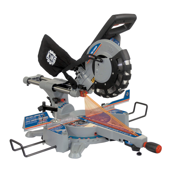
KING CANADA 10” DUAL BEVEL SLIDING 09/2013 COMPOUND MITER SAW WITH TWIN LASER GUIDE *Enhanced Twin Laser Effect MODEL: 8385N INSTRUCTION MANUAL COPYRIGHT © 2013 ALL RIGHTS RESERVED BY KING CANADA TOOLS INC. -
Page 2: Warranty Information
LIMITED TOOL WARRANTY King Canada makes every effort to ensure that this product meets high quality and durability standards. King Canada warrants to the original retail consumer a 2-year limited warranty as of the date the product was purchased at retail and that each product is free from defects in materials. -
Page 3: General Safety Instructions
GENERAL SAFETY INSTRUCTIONS VOLTAGE WARNING: Before connecting the tool to a power source (receptacle, outlet, etc.) be sure the voltage supplied is the same as that specified on the nameplate of the tool. A power source with voltage greater than that for the specified tool can result in SERIOUS INJURY to the user - as well as damage to the tool. -
Page 4: Additional Safety Instructions For Sliding Compound Miter Saws
ADDITIONAL SAFETY INSTRUCTIONS FOR SLIDING COMPOUND MITER SAWS 1. WARNING: USE ONLY CROSS-CUTTING SAW BLADES. 19. MAKE SURE blade is not contacting workpiece before switch is WHEN USING CARBIDE TIPPED BLADES, DO NOT USE turned on. BLADES WITH DEEP GUILLETS AS THEY CAN DEFLECT AND CONTACT GUARD. -
Page 5: Electrical Information
12-16 EXTENSION CORDS FIGURE 2 The use of any extension cord will cause some loss of power. Use the TOOL SPECIFICATIONS Model ......................................8385N Voltage ......................................110V Input power ....................................15 Amp. No load speed ..................................5,000 RPM Blade size..................................10” x 40 teeth Arbor size ......................................5/8”... -
Page 6: Unpacking And Assembly
UNPACKING & ASSEMBLY UNPACKING If you find anything wrong, do not operate the tool until the parts have been replaced or the fault has been rectified. Failure to do so could result in serious personal injury. 1. Remove all loose parts from the carton. 2. - Page 7 ADJUSTMENTS BENCH MOUNTING The saw base has holes to facilitate bench mounting. 1. Fix the saw to a bench using 4 hex. bolts and hex. nuts. 2. If desired, you can mount the saw to a piece of 13mm or thicker plywood which can then be clamped to your work support or moved to other job sites and reclamped.
- Page 8 ADJUSTMENTS SETTING THE BLADE SQUARE WITH THE TABLE 1. Make sure that the electrical plug is removed from the main power supply. 2. Push the saw head down to its lowest position, then pull and turn the head release knob to hold the saw head in the transport position.
- Page 9 ADJUSTMENTS & OPERATIONS USING THE TWIN LASER GUIDE SYSTEM The twin laser guide system is controlled by the laser guide push button switch (A) Fig.14 and will only turn on when the miter saw is plugged into a power source. Warning! Do not stare directly into the laser beams.
-
Page 10: Bevel Cut
OPERATIONS When cutting wide workpieces, you should use the sliding action, unlock the slide lock knob (A) Fig.16. 1. Raise the saw head to its highest position and slide the blade towards you. 2. Hold the handle firmly and squeeze the trigger. Allow the blade to reach maximum speed. 3. - Page 11 REPLACING/INSTALLING BLADE REPLACING/INSTALLING BLADE DANGER! • Never attempt to use a blade larger than the stated capacity of the saw (10”). It will come into contact with the blade guards and housing. • Never use a blade that is too thick to allow the outer blade flange to engage with the flats on the spindle.
-
Page 12: Maintenance
MAINTENANCE MAINTENANCE All the ball bearings are sealed and lubricated for life and will require no maintenance. Cleaning • After use, wipe off chips and dust adhering to the tool with cloth or the like. Keep the blade guards and covers clean . Lubricate the sliding portions with machine oil to prevent rust.
Need help?
Do you have a question about the 8385N and is the answer not in the manual?
Questions and answers