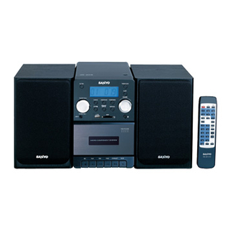
Table of Contents
Advertisement
Service Manual
CONTENTS
Laser Beam Safety Precaution ........................................ 1
Tuner Adjustments ........................................................... 2
Tape Deck Adjustments ................................................... 3
Exploded View (Packing & Accessories) ......................... 4
Exploded View (Cabinet & Chassis) ................................ 5
Parts List .......................................................................... 6
Wiring Connection ............................................................ 9
Schematic Diagram (MAIN) ............................................. 10
Schematic Diagram (CD) ................................................. 12
Schematic Diagram (MCU) .............................................. 14
Micro Component System
Schematic Diagram (TUNER) .......................................... 16
Schematic Diagram (TAPE) ............................................. 17
Schematic Diagram (CONTROL) ..................................... 18
Schematic Diagram (USB/SD) ......................................... 19
Wiring Diagram (CD) ........................................................ 20
Wiring Diagram (CONTROL) ........................................... 22
Wiring Diagram (TUNER) ................................................. 24
Wiring Diagram (TAPE) .................................................... 26
Wiring Diagram (USB/SD) ................................................ 28
Wiring Diagram (MAIN) .................................................... 29
FILE NO.
DC-UB1470
(XE)
PRODUCT CODE No.
129 738 00
SM
REFERENCE No.
2810066
Advertisement
Table of Contents

Summary of Contents for Sanyo DC-UB1470
-
Page 1: Table Of Contents
FILE NO. Service Manual Micro Component System DC-UB1470 (XE) PRODUCT CODE No. CONTENTS 129 738 00 Laser Beam Safety Precaution ........1 Schematic Diagram (TUNER) .......... 16 Tuner Adjustments ............2 Schematic Diagram (TAPE) ..........17 Tape Deck Adjustments ........... 3 Schematic Diagram (CONTROL) ........ -
Page 2: Laser Beam Safety Precaution
RoHS This product does not contain any hazardous substances prohibited by the RoHS Directive. (RoHS compliant product is "R" or "Z" appears at the last digit of serial number or a "RSF" label near the rating plate.) WARNING You are requested to use RoHS compliarit parts for maintenance or repair. You are requested to use lead-free solder. (This product has been manufactured using lead-free solder. -
Page 3: Tuner Adjustments
TUNER ADJUSTMENTS - 2 -... -
Page 4: Tape Deck Adjustments
TAPE DECK ADJUSTMENTS - 3 -... -
Page 5: Exploded View (Packing & Accessories)
EXPLODED VIEW (PACKING & ACCESSORIES) - 4 -... -
Page 6: Exploded View (Cabinet & Chassis)
EXPLODED VIEW (CABINET & CHASSIS) - 5 -... -
Page 7: Parts List
645 094 2112 NET BRACKET 645 094 1788 FFC CABLE 22P, 645 094 2402 SPEAKER GRILLE CLOTH MAIN CN701 TO CD CN710 645 076 1515 SANYO LOGO 645 055 7187 2P HSG, 645 094 2136 RECORDING BD BRACKET MAIN CN404 TO CD DOOR S... - Page 8 PARTS LIST MAIN P.W.BOARD ASSY REF.NO. PART NO. DESCRIPTION 645 073 8296 5P HSG, REF.NO. PART NO. DESCRIPTION MAIN CN402 TO TUNER CN10 645 094 2334 ASSY PWB MAIN (Only initial) 645 094 2389 HSG 7P,MAIN CN401 TO CD CN702 C0460 645 080 4915 ELECT 1000U 16V C0507...
- Page 9 PARTS LIST TUNER P.W.BOARD ASSY USB/SD P.W.BOARD ASSY REF.NO. PART NO. DESCRIPTION REF.NO. PART NO. DESCRIPTION 645 094 2365 ASSY PWB TUNER (Only initial) 645 094 2358 ASSY PWB USB (Only initial) C0108 645 055 6791 POLY CAP 390PF CN601 645 094 1740 8P HEADER CF101 645 051 6467 BAND PASS FILTER...
-
Page 10: Wiring Connection
WIRING CONNECTION - 9 -... -
Page 11: Schematic Diagram (Main)
SCHEMATIC DIAGRAM (MAIN) This is a basic schematic diagram. - 10 - - 11 -... -
Page 12: Schematic Diagram (Cd)
SCHEMATIC DIAGRAM (CD) This is a basic schematic diagram. - 12 - - 13 -... -
Page 13: Schematic Diagram (Mcu)
SCHEMATIC DIAGRAM (MCU) This is a basic schematic diagram. - 14 - - 15 -... -
Page 14: Schematic Diagram (Tuner)
SCHEMATIC DIAGRAM (TUNER) SCHEMATIC DIAGRAM (TAPE) This is a basic schematic diagram. This is a basic schematic diagram. - 16 - - 17 -... -
Page 15: Schematic Diagram (Control)
SCHEMATIC DIAGRAM (CONTROL) SCHEMATIC DIAGRAM (USB/SD) This is a basic schematic diagram. This is a basic schematic diagram. - 18 - - 19 -... -
Page 16: Wiring Diagram (Cd)
WIRING DIAGRAM (CD) - 20 - - 21 -... -
Page 17: Wiring Diagram (Control)
WIRING DIAGRAM (CONTROL) - 22 - - 23 -... -
Page 18: Wiring Diagram (Tuner)
WIRING DIAGRAM (TUNER) - 24 - - 25 -... -
Page 19: Wiring Diagram (Tape)
WIRING DIAGRAM (TAPE) - 26 - - 27 -... -
Page 20: Wiring Diagram (Usb/Sd)
WIRING DIAGRAM (USB/SD) WIRING DIAGRAM (MAIN) SANYO Electric Co., Ltd. May / '07 Printed in Japan Osaka, Japan - 28 - - 29 -...


Need help?
Do you have a question about the DC-UB1470 and is the answer not in the manual?
Questions and answers