Advertisement
© 2014 Thermaltake Technology Co., Ltd. All Rights Reserved. A-2014.10
All other registered trademarks belong to their respective companies.
Tested To Comply
With FCC Standards
FOR HOME OR OFFICE USE
www.thermaltake.com
C
V 1 2
ore
Your Build. Our Core
User's Manual
Benutzerhandbuch
Mode d'emploi
Manual del usuario
Manuale dell'utente
Manual do Utilizador
安裝說明書
用戶手冊
ユーザーズマニュアル
Руководство пользователя
kullanıcı elkitabı
(EEE Yönetmeliğine Uygundur)
คู ่ ม ื อ การใช้
www.thermaltake.com
Advertisement

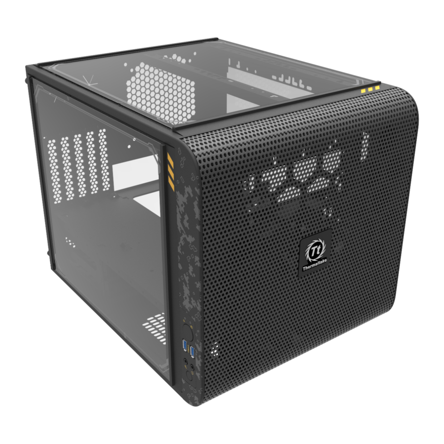
Summary of Contents for Thermaltake Core V21
- Page 1 ユーザーズマニュアル Руководство пользователя kullanıcı elkitabı (EEE Yönetmeliğine Uygundur) คู ่ ม ื อ การใช้ © 2014 Thermaltake Technology Co., Ltd. All Rights Reserved. A-2014.10 All other registered trademarks belong to their respective companies. www.thermaltake.com Tested To Comply With FCC Standards FOR HOME OR OFFICE USE www.thermaltake.com...
-
Page 2: Table Of Contents
5 x 10 mm Cable Management Cable Tie Chapter 4. Other Stacking Screw # 6-32 x 15 mm Thermaltake Power Supply Series (Optional) Flange Nut # 6-32 Stacking *Picture for reference only Stacking Gasket Stacking *Information in the user manual is subject to change without notice... -
Page 3: Warning And Notice
Warning and Notice CPU Cooler Height Limitation VGA ( Add- on card) Length Limitation Atenção!! - Limite de altura para o dissipador do CPU: O limite de altura para o dissipador do CPU é 185 mm (7,3 polegadas). - Limite de comprimento para VGA (placa gráfica): O limite de comprimento para VGA (placa gráfica) é... -
Page 4: Side Panel Disassembly
PSU Installation Side Panel Disassembly English / 1. Place the power supply in proper location and secure it with screws. 2. Place the PSU rubber on bracket. 3. Secure bracket with the case by locking hook. 4. Install the bracket in proper location and secure it with screws. -
Page 5: Motherboard Installation
Motherboard Installation 3.5" & 2.5" HDD Installation 2.5" HDD 3.5" HDD English / 繁體中文 / 1. Pull the HDD tray out. 1. 將硬碟托盤取出 2. Place the 2.5” or 3.5” hard drive on the tray and 2. 將2.5”或3.5”硬碟放置在硬碟托盤上,用螺絲固定 secure it with screws. 硬碟... -
Page 6: Hdd Installation
2.5" HDD Installation PCI Slot Usage English / 繁體中文 / 1. Loosen the screws with a screwdriver. 1. 用螺絲起子將螺絲取下. 2. Install the PCI card in proper location and secure 2. 將擴充卡放置在合適的位置並用螺絲固定。 it with screws. 简体中文 / Deutsch / 1. 用螺丝起子将螺丝取下. 1. - Page 7 Liquid Cooling Installation Air Cooling Installation Fan Support: Radiator Support: Front: 1 x 120mm or 2 x 120mm Front: 1 x 140mm or 2 x 140mm 1 x 120mm or 1 x 240mm 1 x 200mm 1 x 140mm Top: Top: 1 x 120mm or 2 x 120mm or 3 x 120mm 24cm x 1 + 28cm x 1...
-
Page 8: Bracket Installation
I/O Panel Placement Guide Bracket Installation For Air Cooling For Liquid Cooling Mount the fans and radiators on bracket and secure it with screws. Secure the bracket by locking clip Magnetic LOGO Note: Install the bracket in proper location... -
Page 9: Stacking Installation
Stacking Installation Leads Installation English Leads Installation Guide Case LED Connection / On the front of the case, you can find some LEDs and switch leads. Please consult your user manual of your motherboard manufacturer, then connect these leads to the panel header on the motherboard. USB 3.0 connection / 1. -
Page 10: Usb 3.0 Connection
Français Italiano Guide d'installation des fils Guida di installazione dei contatti Connexion des voyants du boîtier / Sur la face avant du boîtier, vous trouverez plusieurs voyants et les fils des Connessione del LED del case / Nella parte anteriore del case, sono presenti alcuni contatti per interruttori e LED. boutons. - Page 11 繁體中文 日本語 線材安裝說明 リード線の取り付けガイド 機殼LED連接方式 / 在機殼前方的面板後面,可以找到一些LED與開關線材(POWER Switch….),請參考主機板使用說明書, ケース LED の接続 / ケース前面には、LEDとスイッチリード線があります。 マザーボードメーカーのユーザーマニュアル 並將機殼上的線材正確地連接到主機板上,這些線材通常都會印有標籤在上面,如果沒有的話,請找出機殼前方面板上線材原 を参照し、これらのリード線をマザーボードのパネルヘッダに接続してください。 本的位置以知道正確的來源。 USB 3.0 の接続 / USB 3.0 連接 / 1. お使いのマザーボードがUSB 3.0接続をサポートしていることを確認してください。 1. 請確認主機板是否支援USB 3.0傳輸介面。 2. 連接USB 3.0傳輸線至主機板上的USB3.0接埠。 2. USB 3.0ケーブルをコンピュータの空いているUSB 3.0ポートに接続します。 音效連接 / 請根據下面的音源接頭圖示與主機板使用手冊來連接音效裝置,請確認主機板上的音效裝置是支援AC' 97音效或是 オーディオ接続...
-
Page 12: Thermaltake Power Supply Series (Optional)
คู ่ ม ื อ การติ ด ตั ้ ง สายไฟ Every power supply units from Thermaltake should pass a very strict quality control before sent to การเชื ่ อ มต่ อ ไฟ LED ของเคส / ที ่ ด ้ า นหน้ า ของเคส คุ ณ จะเห็ น ไฟ LED และสายไฟของสวิ ต ซ์...


Need help?
Do you have a question about the Core V21 and is the answer not in the manual?
Questions and answers