Table of Contents
Advertisement
Service
Manual
SECTION
MR2021 (CD/Tuner Amplifier)
1 TECHNICAL SPECIFICATIONS ............................................................................................................. 1-1
2-1 HOW TO DISASSEMBLE ....................................................................................................................... 2-1
2-2 REPAIR INTRODUCTION ...................................................................................................................... 2-6
2-3 EXPLANATION OF CIRCUITS ............................................................................................................... 2-6
3 SERVICE MODE ..................................................................................................................................... 3-1
4-1 BLOCK DIAGRAM .................................................................................................................................. 4-1
4-2 AM STEREO ADJ.(F ONLY) ................................................................................................................... 4-1
4-3 MICROPROCESSOR DATA ................................................................................................................... 4-1
5 WIRING DIAGRAM ................................................................................................................................. 5-1
6 SCHEMATIC DIAGRAM AND PARTS LOCATION ................................................................................. 6-1
7B TUNER BOARD ECO5 ......................................................................................................................... 7B-1
7D TUNER 95 BOARD .............................................................................................................................. 7D-1
8 CD NAMI 8 BOARD ................................................................................................................................. 8-1
9 EXPLODED VIEW AND PARTS LIST ..................................................................................................... 9-1
10 ELECTRICAL PARTS LIST ................................................................................................................... 10-1
1 EXPLODED VIEW AND PARTS LIST .................................................................................................... 1-1
CAUTION
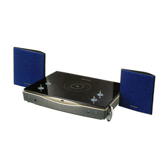
The System MR2020 (Layla) combines MR2021 (CD/Tuner Amplifier) with LS2021 (Speaker System).
Please use this service manual with referring to the user guide ( D.F.U. ) without fail.
Printed in Japan
TABLE OF CONTENTS
system MR2020 / Layla
74 MR2020 /
2G (Layla)
MR2020 F,K,KK,U
CD/Tuner System
4822 725 51183
First Issue 1999.01
298J855010
PAGE
R
MIT
Advertisement
Table of Contents

Related Manuals for Marantz MR2020


Summary of Contents for Marantz MR2020
-
Page 1: Table Of Contents
1 EXPLODED VIEW AND PARTS LIST ....................1-1 CAUTION The System MR2020 (Layla) combines MR2021 (CD/Tuner Amplifier) with LS2021 (Speaker System). Please use this service manual with referring to the user guide ( D.F.U. ) without fail. system MR2020 / Layla 4822 725 51183 First Issue 1999.01... - Page 2 MARANTZ Parts for your equipment are generally available to our National Marantz Subsidiary or Agent. ORDERING PARTS : Parts can be ordered either by mail or by Fax.. In both cases, the correct part number has to be specified.
-
Page 3: Technical Specifications
1. TECHNICAL SPECIFICATIONS FM Tuner Frequency range ............................87.5 ~ 108.0 MHz F only ............................ 76.0~ 90.0 MHz Sensitivity ................................ 21.2 dBf / 3.2 µV S/N (Mono/Stereo) ..............................75 / 43 dB F only ............................70 / 50 dB THD (Mono/Stereo) ..............................1.5 / 1.5 % MW Tuner Frequency range ............................... -
Page 4: How To Disassemble
2-1. HOW TO DISASSEMBLE MR2020 1. Take the bottom case (001G) apart (1) Turn MR2020 upside down by the jig (Refer to fig.1-3). Take care that the top cover will not damaged, especially the 4 levers. If you don't have the jig, you prepare to put some magazine or telephone guide under the MR2020 (The height is over 3cm books). - Page 5 (3) While lifting the bottom case, remove the rear panel as shown in fig.5-6. Fig.5 Lifting the bottom case Fig.6 Removing the rear panel (4) Remove the mains code bush as shown in fig.7. Fig.7 Removing the mains code bush...
- Page 6 (5) Lift up the bottom case, remove the put the one with turning to front side (Refer to fig.8). Fig.8 Taking the bottom case apart Remark for reassemble When you fit the bottom case, remove the lid of the bottom case (Refer to fig.9) and confirm the arrangement of lead lines for transformer.(Refer to fig.10).
- Page 7 2. Take the top panel (001D) apart (1) Turn MR2020 upside down by the jig. (Refer to fig.1-3) Take care that the top cover will not damaged, especially the 4 levers. If you don't have the jig, you prepare to put some magazine or telephone guide under the MR2020.
- Page 8 (3) Turn the MR2020 to its normal operating position. (4) Open the top cover of MR2020 by hand. (5) Take out the 2 screws (M2 type screw) on the top (see fig.15). Fig.15 Positions of 2 screws on the top (6) The upper par t and lower par t of the top cover are connected to each other with adhesive tape.
-
Page 9: Repair Introduction
2-2. REPAIR INTRODUCTION PREPARATION FOR CD BLOCK Set a disc for repair into product. Tur n the product upside down on the jig (Parts No.*MR2021JIG). Take care that the top cover will not damaged, especially the 4 levers. (Refer to "How to disassemble MD2020") For the top panel will not open while repairing, remove the connecting wires of panel motor from the connector... - Page 10 When the bottom case is closing. If the fan revolving starts within 10 minutes, the function is correct working. Otherwise keep outputting 1W from both channels of the product when the bottom case is opening. If the fan revolving starts within 5 minutes, the function is correct working. REMARK Do not output over 1W when the bottom case is open.
- Page 11 Fig.2 POWER CD MODE STOP OR MUTE BUTTON MODE VOLUME ON/OFF TRACK JUMP CHANGE MINIMUM MUTE MUTE2 DSC MUTE TOP PANEL OPEN SENSOR The pulse (T=84msec, Duty 50%) is always added to LED (QU15), from #30Pin of QU10, through RF28 and QU22. Cover the sensor with your fingers, the collector voltage of QU01 goes up over 0.7VP-P .
-
Page 12: Service Mode
3 SERVICE MODE 1. How to set the service mode (1) While holding the CLOCK and CLEAR buttons together, put the mains plug to mains outlet. (2) FL check mode will start. (3) While in FL check mode, each time the FUNCTION button pressed (within 2 seconds), the mode changes in the following order. -
Page 13: Block Diagram
4-1 BLOCK DIAGRAM 4-3 MICROPROCESSOR DATA LINE Pin No. Pin Name Signal Name Active Slow Function ANT. P10 (INT0) _POW_DWN POWER DOWN P11 (INT1) _STANDBY POWER STANDBY P12 (INT2) IN/OUT IIC SDA(for RDS,DSC) P13 (DVO) IIC SCL(for RDS,DSC) DSC_MUTE DSC MUTE _CD_STANDBY CD STANDBY _MUTE2... -
Page 14: Wiring Diagram
5. WIRING DIAGRAM NAMI 8 F ONLY TUNER 95 or ECO 5 CD94V5B1... -
Page 15: Schematic Diagram And Parts Location
6. SCHEMATIC DIAGRAM AND PARTS LOCATION WU09 (FROM JU01) PHONE... - Page 16 002M SPEAKER...
- Page 17 P704 Q708 Q707 Q701 Q702 Q801 Q805 Q806 QD01 Q853 Q705 Q704 Q706 Q703 Q852 Q851 Q803 Q807 PX04 QN03 QN01 QH01 QE04 QE03 QN04 QN02 QX07 QX03 QX08 QE04 QE02 QX70 QX04 QX01 QX02 QX05 QX06 QX09 PX54 P804 PH04...
- Page 18 CD BOARD NAMI 8 PS64 TUNER BOARD TUNER 95 or ECO5...
- Page 19 PU04 QU12 QU13 QU14 QU15 QU22 QU26 QU09 QU10 QU21 QU16 QU17 1U28 QU04 QU03 QU28 QU27 QU06 QU07 QU05 QU08 QU25 QU24 QU23 QU18 QU19 QU20 QF51 PS54 PS04 PS14...
- Page 20 [F] VERSION AM STEREO TUNER BOARD ECO 5 From 1131 PA01 QA01 QA04 QA03 QA02...
-
Page 21: Tuner Board Eco5
7B-1 7B-1 BLOCK DIAGRAM TUNER BOARD ECO 5 systems buffer ampl. Vcc1 Stab Stab Discriminator Vcc2 FM-RF (MPX) 1101 Loop 1124 (1102) LF filter 10,7 MHz 10,7 MHz 10,7 MHz right right Stereo left left Decoder frontend Mixer Det. stereo Version FM-Osc. - Page 22 7B-2 7B-2 TUNER ADJUSTMENT TABLE ( ECO5 FM/MW- and FM/MW/LW - versions with AM-frame aerial ) TUNER ADJUSTMENT TABLE ( ECO5 FM/MW- stereo versions with AM-frame aerial ) Waverange Input frequency Input Tuned to Adjust Output Scope/Voltmeter Waverange Input frequency Input Tuned to Adjust...
- Page 23 7B-3 7B-3 1101 A 1 2106 C2 2137 C5 3149 C5 3173 A 5 5114 C4 5130 A 3 7104 C2 9117 B 2 9129 B 3 2101 C4 2118 B 4 2139 B 2 2153 C3 2166 B 2 3112 A 3 3123 A 3 3143 C2...
- Page 24 7B-4 7B-4 TUNER BOARD ECO5 / Systems 1101 A 1 1102 B 2 1103 D 2 1121 E20 VERSION PROGRAMMING COMPONENTS AM-IF1 AM-IF2 1124 G20 5111 5112 1126 E20 T046 1101 1130 I20 T001 6120 3156 3157 3170 remark 9128 1131 I20 450 kHz 450 kHz...
- Page 25 7B-5 TUNER ECO5 ELECTRICAL PARTSLIST MISCELLANEOUS RESISTORS ––––––––––––––––––––––––––––––––––––––––––––––––––––– ––––––––––––––––––––––––––––––––––––––––––––––––––––– 1101 4822 267 31505 SOCKET 2-POLE CLICKFIT, 300Ω 3142 4822 100 11163 100kΩ TRIMPOT LIN. only for /17 1102 4822 267 10283 SOCKET COAX, IEC 75Ω 3145 © 4822 117 11449 2,2kΩ...
- Page 26 7B-6 TUNER ECO5 for 06 ( Japanese version) ELECTRICAL PARTS LIST ––––––––––––––––––––––––––––––––––––––––––––––––––––– 1102 4822 265 20598 SOCKET COAX YKD31-0468 75Ω 1130 4822 267 10749 CONNECTOR S11B-XH-A (11P) 2111 5322 122 32531 100pF 5%NP0 50V 2153 5322 122 33063 2.2pF 5% NP0 50V 3113 4822 051 10102 1kΩ...
-
Page 27: Tuner 95 Board
7D-1 7D-1 7D-1 BLOCKDIAGRAM IF-AM IF-AM AM-DET 10,7MHz 450kHz 450kHz 450kHz 1121 VCC1 5111 5112 5114 VCC2 TEA5762 VCC1 FM-IF2 V Stab B FM-IF2I V Stab A AM-MIX Out AM-IF1 In AM-IF2 AM-AFC AFC- AFC+ VCC2 FM FRONTEND WRITE Enable ENABLE STABILIZER DATA... - Page 28 7D-2 7D-2 7D-2 1102 2107 2128 2136 2145 2161 3124 3137 3145 3158 3167 3183 5103 5121 7104 9102 9118 TUNER 95 bis Adjustment Table (FM, MW, LW with Frame antenna) 1103 2108 2129 2137 2147 2162 3125 3138 3146 3159 3169 3184...
- Page 29 7D-3 7D-3 1102 1124 2107 2122 2128 2132 2136 2141 2145 2151 2161 3107 3124 3130 3137 3143 3150 3154 3160 3164 3173 3184 3192 5107 5112 5122 6107 7104 7122 1103 1126 2108 2123 2129 2133 2137 2142 2147 2152 2162 3108...
- Page 30 7D-4 7D-4 ELECTRICAL PARTS LIST - TUNER 95 BOARD ELECTRICAL PARTS LIST - TUNER 95 BOARD MISCELLANEOUS 3130 4822 051 10008 0R 5% 0,25W 5114 4822 157 70302 AM-IF Filter 450kHz 1102 4822 267 10283 Socket Coaxial IEC 75R 1103 4822 265 31184 JST Connector 2 pin 3131 4822 051 10008 0R 5% 0,25W...
- Page 31 BLOCK DIAGRAM CD BOARD NAMI 8 TABLE OF CONTENTS Block diagram ..............8-1 Component layout ............8-2 Circuit diagram ..............8-3 Parts list ................8-4...
- Page 32 C201C3 C212B4 C224C4 C238D1 C255C5 C268B4 C451A2 C461A2 F208 L451 C2 Q475B2 R212D3 R224B4 R237A3 R256C5 R267B4 R411A3 R421C2 R456A2 R476C3 C202C3 C213C4 C225B4 C239D1 C256C5 C271C4 C452A2 C475A4 F411 B2 Q201C3 R201C4 R213D3 R225B3 R238A3 R257C5 R268D5 R412B2 R422C2 R457B2 X221B5 C203C4...
- Page 33 C201 C8 J201 B3 R418 I12 C202 C9 J202 F3 R420 I13 C203 D8 J203 B14 R421 I13 CD BOARD NAMI 8 C204 C8 J204 I14 R422 I13 C205 C9 J205 F14 R425 I7 CD94V5B1 C206 C9 J206 A14 R426 I7 C207 D8 L221 B9 R451 J9...
- Page 34 (VERS. :VERSION, U:U.S.A., F:JAPAN, K:FAR EAST, ** :EUROPE) (VERS. :VERSION, U:U.S.A., F:JAPAN, K:FAR EAST, ** :EUROPE) POS. VERS. PART NO. POS. VERS. PART NO. POS. VERS. PART NO. PART NO. PART NO. PART NO. DESCRIPTION DESCRIPTION DESCRIPTION COLOR (FOR PCS) COLOR COLOR (FOR PCS)
-
Page 35: Exploded View And Parts List
001T /2 4822 736 16729 USER GUIDE 298J851310 004S F,U CUSHION R 298J809020 001T U USER GUIDE 298J851250 020S F MASTER CARTON CASE 298J801030 MR2020 Z001 REMOTE COMMANDER ZK298J0010 RC2020MR 010T CLAMPER ASSY 298J005500 014T F USER?S CARD 145J865210 020T F... - Page 36 (VERS. :VERSION, U:U.S.A., F:JAPAN, K:FAR EAST, ** :EUROPE) POS. VERS. PART NO. POS. VERS. PART NO. PART NO. PART NO. DESCRIPTION DESCRIPTION COLOR COLOR (FOR PCS) (FOR PCS) (MJI) (MJI) 001B F,K,KK, FRONT PANEL ASSY 298J248510 901G U REAR PANEL 298J250030 917G 4822 532 60948 BUSHING AC MAINS...
- Page 37 0 3 7 G SYMBOL ST YL E PART S NAME 0 3 1 B 0 0 3 B PANEL ASSY. ( 0 2 9 M) ( 0 0 2 M) 0 0 1 B 5 1 1 0 + B. H. M. SCREW ( 0 2 5 M) U ONL Y 5 1 2 5...
-
Page 38: Electrical Parts List
10-1 10-1 (VERS. :VERSION, U:U.S.A., F:JAPAN, K:FAR EAST, ** :EUROPE) 10. ELECTRICAL PARTS LIST NOTE ON SAFETY FOR FUSIBLE RESISTOR : ASSIGNMENT OF COMMON P ARTS CODES. POS. VERS. PART NO. POS. VERS. PART NO. PART NO. PART NO. DESCRIPTION DESCRIPTION COLOR (FOR PCS) - Page 39 10-2 (VERS. :VERSION, U:U.S.A., F:JAPAN, K:FAR EAST, ** :EUROPE) POS. VERS. PART NO. POS. VERS. PART NO. PART NO. PART NO. DESCRIPTION DESCRIPTION COLOR COLOR (FOR PCS) (FOR PCS) (MJI) (MJI) PA04-AM-STEREO PS04-SW ASSY CIRCUIT BOARD [F Version] CIRCUIT BOARD PA04-CAPACITORS SS01 4822 276 14088 TACT SW.
- Page 40 4822 122 40617 CER. 0.1µF +80%-20% 50V DD38104010 QU10 4822 209 17376 MICROPROCESSOR HU298JT000 CU59 4822 124 40786 ELECT 2.2µF 50V EJ22505010 TMP87CS71F MR2020 E3E5 CU61 QU14 4822 130 42682 DIG.TRS. DTA144ES UN4113 BA10002000 4822 126 10408 CER. 220P ±10% 50V DA16221110 47K 47K CU64 QU16 4822 130 41947 TRS.
- Page 41 10-4 (VERS. :VERSION, U:U.S.A., F:JAPAN, K:FAR EAST, ** :EUROPE) POS. VERS. PART NO. POS. VERS. PART NO. PART NO. PART NO. DESCRIPTION DESCRIPTION COLOR COLOR (FOR PCS) (FOR PCS) (MJI) (MJI) CE45 4822 122 30043 CER. 0.01µF +80%-20% 50V DK18103310 QX01 4822 209 83631 IC NJM4558D-D HC10008090...
-
Page 42: Ls2021 ( Speaker System )
Service 74 LS2021 / LS2021 F,K,KK,U Manual Speaker System (VERS. :VERSION, U:U.S.A., F:JAPAN, K:FAR EAST, /X : EUROPE) POS. VERS. PART NO. PART NO. DESCRIPTION COLOR (FOR PCS) (MJI) LS01 4822 240 10354 LOUDSPEAKER, TWEETER QK000030R LS02 4822 240 10355 LOUDSPEAKER, WOOFER QK000040R LS03 4822 265 11569 SPEAKER TERMINAL...
Need help?
Do you have a question about the MR2020 and is the answer not in the manual?
Questions and answers