Table of Contents
Advertisement
Advertisement
Table of Contents

Related Manuals for JTS CS-1


Summary of Contents for JTS CS-1
-
Page 3: Table Of Contents
Important Cautions Features Specification 3.1 Control and power supply unit (CU) 3.2 Delegate and Chairman unit Preparing Procedure 4.1 Connecting between the delegate and chairman units 4.2 Connecting up to 150 unit 4.3 Connecting an external microphone 4.4 Connecting a wireless microphone 4.5 Recording | Playing back the discussion 4.6 Connecting a PA-system | other external equipment 4.7 Connecting a telephone coupler... -
Page 4: Important Cautions
• Keep the devices away from fire and heat sources. • Hot swapping is forbidden. Features The innovative CS-1 i-Conference Discussion System is equipped with JTS in-house made ECM capsule, intelligent automatic mixing technology and integrated acoustic and mechanical design, providing Turn-Key solution and deliv- ering consistently natural, feedback-free audio performance with any environment. -
Page 5: Specification
Specification 3.1 Control and power supply unit (CU) 3.1.1 Front Panel 1) Power On/Off switch 2) LCD display: setting and displaying mode status, simul- taneously maximum user number, and date. 3) Set button: pressing “set” button to enter setting mode on the LCD panel. - Page 6 3.1.2 Rear Panel 1) DCV input: 2) Insertion input and output switch: default setting is “In”, when switching to“In”, all internal speaker will be muted, and switch to external audio device. 3) Telephone coupler input and output: 4) Insertion input and output: connect to an external audio equalizer for speech quality improvement.
-
Page 7: Delegate And Chairman Unit
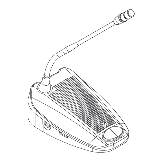
3.1.3 LCD Display 1) Mode status: show the discussion mode 2) Simultaneously user number: the maximum number of simultaneously active users is four. 3) Date | Set: While setting, “Set” will flash. 4) Time: 3.2 Delegate and Chairman unit 1) Gooseneck Microphone 2) Two 3.5mm stereo headphone sockets 3) Rotary volume control: control the volume level of the headphone. - Page 8 Delegate Chairman unit...
-
Page 9: Preparing Procedure
The i-Conference discussion system can be used with up to 150 units by adding maximum 2 additional CUs functioning as power supply units only. The system is controlled by the master CS-1 CU. The cables necessary for these connections can be delivered by your local dealer. -
Page 10: Connecting An External Microphone
4.3 Connecting an external microphone 1) Put the external microphone connector into the micro- phone XLR input of the CU. 2) Adjust the sensitivity by using the gain control 2. Caution: Always use the microphone with balanced output. The microphone XLR input provides a 12V phantom power supply. -
Page 11: Recording | Playing Back The Discussion
4.5 Recording | Playing back the discussion Voltage: 1) Connect a recorder to the recorder input and output by two pairs of RCA cable. 2) Adjust the sensitivity by using the gain control 1 4.6 Connecting a PA-system | other external equipment 1) Connect audio sources to the line input by a RCA cable. -
Page 12: Connecting A Telephone Coupler
2) The telephone coupler would further connect to the telephone wall socket and a telephone. Caution: Never try to connect a telephone directly to CS-1 i-Confer- ence Discussion system. A telephone coupler could provide adequate isolation between the telephone network and the CS-1 i-Conference Discussion System. -
Page 13: Connecting Power Cord
4.9 Connecting power cord 1) Using the supplied power cord set to connect the CU to the power supply socket. 2) Press Power ON/OFF switch to turn on the system. As soon as the power is on, the LCD Display will light up. -
Page 14: Operation
Operation 5.1 System testing 1) Pressing the “Set” button over 1.5 seconds, the Date | Set area on the LCD Display will flash and show “Set”. 2) Press “Up” or “Down” button to choose “System Test” on the Mode Status area of the LCD Display. 3) All connected chairman and delegate units will light up. -
Page 15: Counter Operation
5.4 Counter Operation 1) Pressing the “Set” button, the Date | Set area on the LED- Display will show“Counter” 2) Pressing “Up” to start counting. 3) Pressing “Up” again to stop. 4) Pressing “Down” to clear data after stopping. 5) Pressing the “Set” button again to jump back the original display. -
Page 16: Chairman Unit Operation
5.6 Chairman unit operation 1) Independent of the setting of the microphone mode on the CU, pressing the microphone ON/OFF” push-button will activate the gooseneck microphone on the chairman unit. 2) Pressing again turns the microphone off. 3) Pressing and holding the chairman priority button will deactivate all active delegate units and activate the chair- man microphone. -
Page 17: Volume Control Of Headphone And Internal Speaker Of Cu
5.8 Volume control of headphone and internal speaker of CU 1) While using internal speaker or headphone to monitor the discussion, turning the monitor volume control to adjust the volume of them. 2) The maximum volume level is controlled by the speaker volume control of CU 5.9 Using a headphone 1) Connecting the headphones to the left and/or right side... -
Page 18: Open Mode
5.10 Open mode 1) Pressing the “Set” button over 1.5 seconds, the Date | Set area on the LCD Display will flash and show “Set”. 2) Press “Up” or “Down” button to choose “Open Mode” on the Mode Status area of the LCD Display. 3) Press “Set”... -
Page 19: Override Mode
5.12 Override mode 1) Selecting the “Override mode” as the 5.10 procedures. Under “Override mode”, the system only allow one delegate unit be activated. Press the microphone ON/OFF push-but- ton on one delegate unit will deactivate the previous active delegate unit, and activate its own microphone 5.13 Chairman only mode 1) Selecting the “Chairman only mode”... -
Page 20: Technical Data
Headphone output • Output level: -8dBV/+2dBV • Output Impedance: 22Ω System limits Number of delegate/chairman units connected to CU • Maximum in total: 50 • Maximum per Trunk output: 25 • Maximum trunk length using CS-1: standard cabling: 100m (328 ft) -
Page 21: Mechanical Specifications
6.1.2 CS-1CH & DU Gooseneck Microphone: • Type: Back Electret Condenser • Frequency Response: 50 to 18,000Hz • Polar Pattern: Cardioid • Max. SPL for 1% THD: 125dB • Gooseneck Length: 15” (400mm) 6.2 Mechanical Specifications 6.2.1 CS-1CU Dimensions (HxWxD) : 360*150*90 mm Weight : 1745 g 6.2.2 CS-1CH &... -
Page 22: Pin Configuration
6.4 Pin configuration Power CINCH Trunk External Connector Connector Connections Microphone (XLR) Trunk Connections 1) Audio contribution line 2) GND 3) Audio distribution line 4) Control line 1 5) Control line 2 6) V+ supply 7) V- supply External Microphone (XLR) 1) GND (0V, phantom supply) 2) Signal + (+12V, Phantom supply) 3) Signal –... - Page 24 59508-012-04...
Need help?
Do you have a question about the CS-1 and is the answer not in the manual?
Questions and answers