Advertisement
Save this instructions for future use!
FAILURE TO READ AND FOLLOW ALL INSTRUCTIONS
CAREFULLY BEFORE INSTALLING OR OPERATING THIS
CONTROL COULD CAUSE PERSONAL INJURY AND/OR
PROPERTY DAMAGE.
APPLICATIONS
THERMOSTAT APPLICATION GUIDE
Description
Heat Pump (No Aux . or Emergency Heat)
Heat Pump (with Aux . or Emergency Heat)
Systems with up to 3 Stages Heat, 2 Stages Cool
Heat Only Systems
Cool Only Systems
Wired Remote Temperature Sensor (Indoor/Outdoor)
Dual Fuel Feature (Heat Pump Mode)
SPECIFICATIONS
Electrical Rating:
Battery Power . . . . . . . . . . . . . . . . . . . . . . . . . . mV to 30 VAC, NEC Class II, 50/60 Hz or DC
Input-Hardwire . . . . . . . . . . . . . . . . . . . . . . . . . 20 to 30 VAC
Terminal Load . . . . . . . . . . . . . . . . . . . . . . . . . . . . . 1 .5A per terminal, 2 .5A maximum all terminals combined
Setpoint Range . . . . . . . . . . . . . . . . . . . . . . . . . . . . 45 to 99°F (7 to 37°C)
Differential (Single Stage) . . . . . . . . . . . . . . . . . . . . Heat 0 .6°F; Cool 1 .2°F
Differential (Multi-Stage) . . . . . . . . . . . . . . . . . . . . . Heat 0 .6°F; Cool 1 .2°F
Differential (Heat Pump) . . . . . . . . . . . . . . . . . . . . . Heat 1 .2°F; Cool 1 .5°F
Operating Ambient . . . . . . . . . . . . . . . . . . . . . . . . . . 32°F to +105°F (0 to +41°C)
Operating Humidity . . . . . . . . . . . . . . . . . . . . . . . . . 90% non-condensing max .
Shipping Temperature Range . . . . . . . . . . . . . . . . . -40 to +150°F (-40 to +65°C)
Dimensions Thermostat . . . . . . . . . . . . . . . . . . . . . . 4-9/16"H x 5-13/16"W x 1-3/16"D
CAUTION
!
To prevent electrical shock and/or equipment damage,
disconnect electric power to system at main fuse or
circuit breaker box until installation is complete.
Index
Thermostat with Automatic
Heat/Cool Changeover Option
Heat Pump Installation and Operating Instructions
Non-Programmable
Yes
Yes
Yes
Yes
Yes
Yes
Yes
ATTENTION: MERCURY NOTICE
This product does not contain mercury . However, this
product may replace a product that contains mercury .
Mercury and products containing mercury must not be
discarded in household trash . Do not touch any spilled
mercury . Wearing non-absorbent gloves, clean up any spilled
Page
mercury and place in a sealed container . For proper disposal
2
of a product containing mercury or a sealed container of
spilled mercury, place it in a suitable shipping container .
3
Refer to http://thermostat-recycle .org for location to send
3
the product containing mercury .
4
5
8
8
12
Programming Choices
5/1/1 Day
PART NO. 37-7194C
Replaces 37-7194B
7 Day
1045
Advertisement
Table of Contents

Subscribe to Our Youtube Channel
Related Manuals for Water Furnace TP32W03


Summary of Contents for Water Furnace TP32W03
-
Page 1: Table Of Contents
Thermostat with Automatic Heat/Cool Changeover Option Heat Pump Installation and Operating Instructions Save this instructions for future use! Programming Choices FAILURE TO READ AND FOLLOW ALL INSTRUCTIONS CAREFULLY BEFORE INSTALLING OR OPERATING THIS Non-Programmable 5/1/1 Day 7 Day CONTROL COULD CAUSE PERSONAL INJURY AND/OR PROPERTY DAMAGE. -
Page 2: Installation
INSTALLATION Battery Location WARNING 2 "AA" alkaline batteries are included in the thermostat at Thermostat installation and all components of the the factory with a battery tag to prevent power drainage . control system shall conform to Class II circuits per Remove the battery tag to engage the batteries . -
Page 3: Wiring Connections
WIRING CONNECTIONS Refer to equipment manufacturers' instructions for specific Wiring diagrams shown are for typical systems and describe system wiring information . After wiring, see CONFIGURA- the thermostat terminal functions . TION section for proper thermostat configuration . TERMINAL DESIGNATION DESCRIPTIONS Terminal Designation Description B . -
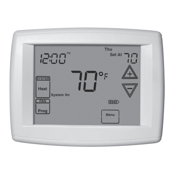
Page 4: Thermostat Quick Reference
THERMOSTAT QUICK REFERENCE Home Screen Description Figure 2 – Home Screen Display Room Temperature Day of Week Set Temperature Time of Day Temperature UP/Down used for System modifying set point Switch as well as to navigating the menus Enters comfort Switch temperature settings into the schedule... -
Page 5: Installer Configuration Menu
INSTALLER/CONFIGURATION MENU To enter the menu: Press the Menu touch key . Press and hold for 5 seconds the Installer Config touch key . This displays menu item #1 in the table below . Press to advance to the next menu item or to return to a previous menu item . - Page 6 INSTALLER/CONFIGURATION MENU This control can be configured for: When C terminal is not powered (battery only), dL On HP1 – Heat Pump with one stage of compressor enables the momentary backlight whenever a key is (2 heat/1 cool) pressed . HP2 –...
- Page 7 INSTALLER/CONFIGURATION MENU (2°C) or more above the actual temperature using 21) Cool Temperature Limit Range – This feature adjusts second stage will energize immediately . With FA OFF, the lowest setpoint temperature for cool . The default second stage will not energize until the setpoint tempera- setting is 45°F .
-
Page 8: Operating Your Thermostat
OPERATING YOUR THERMOSTAT IMPORTANT! Manual Operation (Bypassing the Program) Choose the Fan Setting (Auto or On or Prog) Programmable Mode Fan Auto is the most commonly selected setting and runs the Press and the HOLD button and adjust the tempera- fan only when the heating or cooling system is on . -
Page 9: Enter The Cooling Program
PROGRAMMING Programming Tip: Copy Program Enter the Cooling Program When programming your thermostat, you may copy the pro- 1) Press the SYSTEM button until the Cool icon appears . gram from one day to another day or group of days using the 2) Follow Enter Heating Program instructions for entering Copy key . - Page 10 PROGRAMMING Energy Saving Factory Pre-Program The thermostats are programmed with the energy saving settings shown in the table below for all days of the week . If this pro- gram suits your needs, simply set the thermostat clock and press the RUN button . The table below shows the factory set heating and cooling schedule for all days of the week .
-
Page 11: Wired Remote Temperature Sensing
PROGRAMMING Wired Remote Temperature Sensing Example: Local sensor temperature is 80° and the remote One remote temperature sensor can be installed indoor or sensor is 70° . outdoor and connected to the thermostat by a maximum If weight is selected H4, the averaged temperature of 72° will cable length of 100 meters (300 feet) . -
Page 12: Troubleshooting
TROUBLESHOOTING Reset Operation replace the wires and batteries . If the thermostat has been reset and Note: When thermostat is reset, installer configuration menu settings still does not function correctly contact your heating/cooling service person or place of purchase . and programming will reset to factory settings .
Need help?
Do you have a question about the TP32W03 and is the answer not in the manual?
Questions and answers