
Subscribe to Our Youtube Channel
Related Manuals for Miller Blue Thunder Series


Summary of Contents for Miller Blue Thunder Series
- Page 1 OM-233 381L 2015−06 Processes Stick (SMAW) Welding Description Arc Welding Power Source Blue Thunder Series CE Models Models: 253, 343, 403, 443 Visit our website at www.MillerWelds.com...
- Page 2 From Miller to You Thank you and congratulations on choosing Miller. Now you can get the job done and get it done right. We know you don’t have time to do it any other way. That’s why when Niels Miller first started building arc welders in 1929, he made sure his products offered long-lasting value and superior quality.
-
Page 3: Table Of Contents
TABLE OF CONTENTS SECTION 1 − SAFETY PRECAUTIONS - READ BEFORE USING ........1-1. -
Page 4: Declaration Of Conformity
DECLARATION OF CONFORMITY for European Community (CE marked) products. ITW Welding Italy S.r.l Via Privata Iseo 6/E, 20098 San Giuliano M.se, (MI) Italy declares that the prod uct(s) identified in this declaration conform to the essential requirements and provisions of the stat ed Council Directive(s) and Standard(s). -
Page 5: Section 1 − Safety Precautions - Read Before Using
SECTION 1 − SAFETY PRECAUTIONS - READ BEFORE USING som 2013−09 Protect yourself and others from injury — read, follow, and save these important safety precautions and operating instructions. 1-1. Symbol Usage DANGER! − Indicates a hazardous situation which, if Indicates special instructions. - Page 6 D Remove stick electrode from holder or cut off welding wire at FUMES AND GASES can be hazardous. contact tip when not in use. D Wear body protection made from durable, flame−resistant material Welding produces fumes and gases. Breathing (leather, heavy cotton, wool). Body protection includes oil-free these fumes and gases can be hazardous to your clothing such as leather gloves, heavy shirt, cuffless trousers, high health.
-
Page 7: Additional Symbols For Installation, Operation, And Maintenance
1-3. Additional Symbols For Installation, Operation, And Maintenance FIRE OR EXPLOSION hazard. MOVING PARTS can injure. D Do not install or place unit on, over, or near D Keep away from moving parts such as fans. combustible surfaces. D Keep all doors, panels, covers, and guards D Do not install unit near flammables. -
Page 8: California Proposition 65 Warnings
1-4. California Proposition 65 Warnings Welding or cutting equipment produces fumes or gases This product contains chemicals, including lead, known to which contain chemicals known to the State of California to the state of California to cause cancer, birth defects, or other cause birth defects and, in some cases, cancer. -
Page 9: Section 2 − Definitions
SECTION 2 − DEFINITIONS 2-1. Additional Safety Symbols And Definitions Warning! Watch Out! There are possible hazards as shown by the symbols. Safe1 2012−05 Wear dry insulating gloves. Do not touch electrode with bare hand. Do not wear wet or damaged gloves. Safe2 2012−05 Protect yourself from electric shock by insulating yourself from work and ground. - Page 10 Do not weld on drums or any closed containers. Safe16 2012−05 Do not discard product (where applicable) with general waste. Reuse or recycle Waste Electrical and Electronic Equipment (WEEE) by disposing at a designated collection facility. Contact your local recycling office or your local distributor for further information. Safe37 2012−05 Disconnect input plug or power before working on machine.
-
Page 11: Miscellaneous Symbols And Definitions
2-2. Miscellaneous Symbols And Definitions Shielded Metal Three Phase Amperage Arc Welding Transformer (SMAW) Rectifier Negative Weld Rated No-Load Input Output Terminal Voltage (OCV) Positive Weld Rated Supply Remote Output Terminal Voltage Protective Earth Output Fuse (Ground) Supplementary Constant Current Line Connection Protector (CC) -
Page 12: Section 3 − Specifications
SECTION 3 − SPECIFICATIONS 3-1. Serial Number And Rating Label Location The serial number and rating information for this product is located on the back . Use rating label to determine input power requirements and/or rated output. For future reference, write serial number in space provided on back cover of this manual. 3-2. -
Page 13: Volt-Ampere Curves
3-4. Volt-Ampere Curves The volt-ampere curves show the nor- mal minimum and maximum voltage and amperage output capabilities of the unit. Model 253 Model 343 100 150 200 250 300 350 400 450 100 150 200 250 300 350 400 450 DC AMPERES DC AMPERES Model 443... -
Page 14: Duty Cycle And Overheating
3-5. Duty Cycle and Overheating Duty Cycle is percentage of 10 min- utes that unit can weld at rated load without overheating. If unit overheats, thermostat(s) opens, output stops, and cooling fan runs. Wait fifteen minutes for unit to cool. Reduce amperage or duty cycle before welding. -
Page 15: Section 4 − Installation
SECTION 4 − INSTALLATION 4-1. Selecting A Location Movement Do not move or operate unit where it could tip. Location And Airflow Special installation may be required where gasoline or volatile liquids are present − see NEC Article 511 or CEC Section 20. -
Page 16: Selecting Cable Sizes
4-2. Selecting Cable Sizes* NOTICE − The Total Cable Length in Weld Circuit (see table below) is the combined length of both weld cables. For example, if the power source is 30 m (100 ft) from the workpiece, the total cable length in the weld circuit is 60 m (2 cables x 30 m). Use the 60 m (200 ft) column to determine cable size. -
Page 17: Positioning Jumper Links
4-5. Positioning Jumper Links Check input voltage available at site. 230/400 Volt Models Jumper Links Access Remove side panel. 230 V 400 V Jumper Link Label Check label − only one is on unit. Input Voltage Jumper Links Move jumper links to match input voltage. -
Page 18: Connecting 3-Phase Input Power
4-7. Connecting 3-Phase Input Power = GND/PE Earth Ground Tools Needed: input2 2012−05 − Ref. 803 766-C OM-233 381 Page 14... - Page 19 4-7. Connecting 3-Phase Input Power (Continued) age available at site. Connect green or green/yellow grounding Installation must meet all National and conductor to disconnect device grounding ter- Local Codes − have only qualified per- NOTICE − Verify jumper links match input minal first.
-
Page 20: Section 5 − Operation
SECTION 5 − OPERATION 5-1. Controls Welding Current Indicator Weld Current Control + Positive Weld Terminal − Negative Weld Terminal Power On-Off Switch Power On Pilot Light 804 944 Notes Work like a Pro! Pros weld and cut safely. Read the safety rules at the beginning of this manual. -
Page 21: Section 6 − Maintenance And Troubleshooting
SECTION 6 − MAINTENANCE AND TROUBLESHOOTING 6-1. Routine Maintenance Disconnect power before maintaining. n = Check Z = Change ~ = Clean l = Replace * To be done by Factory Authorized Service Agent Every Months l Damaged Or l Cracked Weld cables ~n Weld Connections Unreadable Labels Every... -
Page 22: Section 7 − Electrical Diagrams
SECTION 7 − ELECTRICAL DIAGRAMS S9215019 Figure 7-1. Circuit Diagram For Blue Thunder 253 And 403 Models (230/400 V) OM-233 381 Page 18... - Page 23 S9215020 Figure 7-2. Circuit Diagram For Blue Thunder 253 And 403 Models (380/520 V) OM-233 381 Page 19...
- Page 24 S9215023 Figure 7-3. Circuit Diagram For Blue Thunder 343 And 443 Models (230/400 V) OM-233 381 Page 20...
- Page 25 S9215018 Figure 7-4. Circuit Diagram For Blue Thunder 343 And 443 Models (380/520 V) OM-233 381 Page 21...
-
Page 26: Section 8 − Parts List
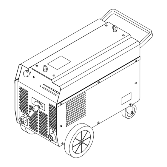
SECTION 8 − PARTS LIST Hardware is common and not available unless listed. 804 964 Figure 8-1. Blue Thunder 253 OM-233 381 Page 22... - Page 27 Dia. Item Part Mkgs. Description Quantity Figure 8-1. Blue Thunder 253 ....+156121032 . . . Upper Panel ..........
- Page 28 Hardware is common and not available unless listed. 804 963 Figure 8-2. Blue Thunder 343 OM-233 381 Page 24...
- Page 29 Item Dia. Part Description Quantity Mkgs. Figure 8-2. Blue Thunder 343 ....+156121032 . . . Upper Panel ..........
- Page 30 Hardware is common and not available unless listed. 804 963 Figure 8-3. Blue Thunder 403 OM-233 381 Page 26...
- Page 31 Dia. Item Part Mkgs. Description Quantity Figure 8-3. Blue Thunder 403 ....+156121032 . . . Upper Panel ..........
- Page 32 Hardware is common and not available unless listed. 804 962 Figure 8-4. Blue Thunder 443 OM-233 381 Page 28...
- Page 33 Item Dia. Part Description Quantity Mkgs. Figure 8-4. Blue Thunder 443 ....+156121033 . . . Upper Panel ..........
- Page 35 Effective January 1, 2015 (Equipment with a serial number preface of MF or newer) This limited warranty supersedes all previous Miller warranties and is exclusive with no other guarantees or warranties expressed or implied. LIMITED WARRANTY − Subject to the terms and conditions 90 Days —...
- Page 36 File a claim for loss or damage during Phone: 39 (0) 2982901 Fax: 39 (0) 298290-203 shipment. email: miller@itw−welding.it For assistance in filing or settling claims, contact your distributor and/or equipment manufacturer’s Transportation Department. © ORIGINAL INSTRUCTIONS − PRINTED IN USA 2015 Miller Electric Mfg. Co. 2015−01...
Need help?
Do you have a question about the Blue Thunder Series and is the answer not in the manual?
Questions and answers