Sign In
Upload
Download
Table of Contents
Contents
Add to my manuals
Delete from my manuals
Share
URL of this page:
HTML Link:
Bookmark this page
Add
Manual will be automatically added to "My Manuals"
Print this page
×
Bookmark added
×
Added to my manuals
Manuals
Brands
Samsung Manuals
Refrigerator
SR-L677EV
Service manual
Samsung SR-L677EV Service Manual
Hide thumbs
Also See for SR-L677EV
:
Owner's instructions manual
(22 pages)
1
2
3
4
5
6
7
8
9
10
11
12
13
14
15
16
17
18
19
20
21
22
23
24
25
26
27
28
29
30
31
32
33
34
35
36
37
38
39
40
41
42
43
44
45
46
47
48
49
50
51
52
53
54
55
56
57
58
59
60
61
62
63
64
65
66
67
68
69
70
71
72
73
74
75
76
77
78
79
80
81
Table Of Contents
82
page
of
82
Go
/
82
Contents
Table of Contents
Troubleshooting
Bookmarks
Table of Contents
Table of Contents
Precautions
Electrical Part Specifications & Standard
Product Specifications
Circuit Diagram
Function & Operating Instruction
Product Dimension
Part Name & Disassembly
Circulation of Refrigerant (H.M CYCLE)
Cool Air Circulation
Display Design
Temperature Control and Other Capacity Explanation
Temperature Control Function
Temperature Selection of Refrigerator Compartment
Quick Cool
Quick Freeze
Alarm When Door Is Open
Buzzer Alarm Function
Forced Running Alarm and Forced Defrost Alarm (Beep Sound)
Sabbath Function
Function of Forced Running
Function of Initial Power on
Power Failure Compensating Function
Test Function
Exhibition Mode
Self-Test Function
Self-Test Function During Normal Activation
Display Function of the Presently Operating Parts
Display Table of Self Diagnosis
Actual Temperature and Selected Temperature in Display Function
Initial Power on
Stability in Inner Temperature
Defrost Display Function
Door Open
PCB Part List
Circuit Descriptions
Power Circuit
Door S/W Detector
Oscillator
Reset Circuit
Temperature Sensor
Button Scan and Display Circuitry
Load Operation
Freezer Temperature Shift
Option Table
Other Option Functions
Refrigerator Temperature Shift
No Power
Trouble Shooting
Problem with Outside Temperature Sensor
Problem with Refrigerator Temperature Sensor
Problem with Self-Test
Problem in Freezer Temperature Sensor
Problem in Refrigerator Defrost Sensor
Problem in Freezer Defrost Sensor
Compressor Does Not Run
When Cooling Fan Do Not Activate
When Freezer Fan (F-Fan) Do Not Activate
When Refrigerator Fan (R-Fan) Do Not Activate
When COMP Cooling Fan Do Not Activate
No Defrosting
If Melody Alarm Runs Continuously
When Alarm Run Continuously
If Beep Sounds Continuously
When Original Panel PCB Do Not Activate
When Buttons of Panel PCB Is Not Selected
When the Light Dosen’t Come on in the Refrigerator
Inspection of Relay
Reference
The Connection of DOOR-CABI
Check for Malfunctioning of the Subordinate
Inspection of the Sensor
Checking the Door S/W
Forced Running & Forced Defrosting
Sensor Partial Pressure Resistance
Exploed View
Freezer Room
Refrigeration Room
Door Parts
Cabinet Parts & Unit
Disassembly & Assembly
Replacement of Refrigerator Fluorescent Lamp
Replacement of Refrigerator Lamp
Replacement of Freezer Lamp
Disassembly of the Cooling Cycle in the Refrigeration Room
Cooling Cycle Unit Assembly in the Refrigeration Compartment
Dust Assembly in the Refrigeration Compartment
Disassembly of the Cooling Cycle Unit in the Freezer
Assembly of the Cooling Cycle Unit in the Freezer
Assembly of Mechanic Compartment in the Refrigerator
Electric Box Assembly
Temperature Controller Disassembly
PCB Circuit Diagram
3-Terminal 1A Positive Voltage Regulators
Absolute Maximum Ratings
Regulator
Specifications of Main Components
Electrical Characteristics Mc7812
Regulator(Mc7812C)
Description
Features
Internal Block Diagram
NPN Epitaxial Silicon Transistor
Switching Application
3.3V Voltage Detector
Absolute Maximum Rating
Electrical Characteristics
Advertisement
Quick Links
1
Product Specifications
2
Electrical Part Specifications & Standard
3
Trouble Shooting
Download this manual
GREEN
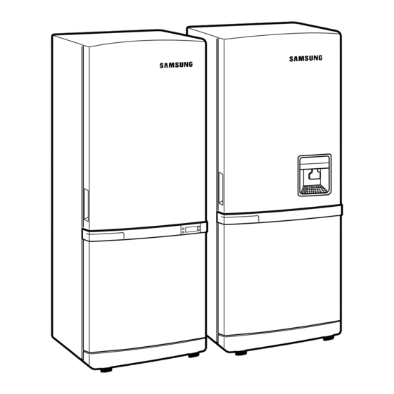
REFRIGERATOR
REFRIGERATOR
Model : SR-L677EV
9. Disassembly & Assembly
10. PCB Circuit Diagram
SR-L677EV
SR-L679EV
11. PCB Parts List
SR-L627EV
SR-L629EV
12. Specifications of Main Components
SR-L679EV
SR-L627EV
SR-L629EV
CONTENTS
1. Precautions
2. Product Specifications
3. Electrical Part Specifications & Standard
4. Circuit Diagram
5. Functions & Operating Instruction
6. Circuit Descriptions
7. Trouble shooting
8. Exploed View
Table of
Contents
Previous
Page
Next
Page
1
2
3
4
5
Advertisement
Table of Contents
Need help?
Do you have a question about the SR-L677EV and is the answer not in the manual?
Ask a question
Questions and answers
Related Manuals for Samsung SR-L677EV
Refrigerator Samsung SR-L62 series Owner's Instructions Manual
Samsung refrigerator owner's instructions (22 pages)
Refrigerator Samsung SR-L627EV Service Manual
(82 pages)
Refrigerator Samsung SR-L626EV Owner's Instructions Manual
(34 pages)
Refrigerator Samsung SR-L676EV Service Manual
(60 pages)
Refrigerator Samsung SR-L629EV Service Manual
(82 pages)
Refrigerator Samsung SR-L679EV Service Manual
(82 pages)
Refrigerator Samsung SR-L678EV Service Manual
(60 pages)
Refrigerator Samsung SR-L36 series Owner's Instructions Manual
Samsung freezer user manual (19 pages)
Refrigerator Samsung SR-L39 series Owner's Instructions Manual
Samsung freezer user manual (19 pages)
Refrigerator Samsung SRL3928B(A) Service Manual
(52 pages)
Refrigerator Samsung RL36EBMS Owner's Instructions Manual
(19 pages)
Refrigerator Samsung RB29F Series User Manual
Samsung refrigerator user manual (17 pages)
Refrigerator Samsung SRL349MW User Manual
(32 pages)
Refrigerator Samsung SRL457MW User Manual
458l bottom mount fridge (21 pages)
Refrigerator Samsung SRL336NW User Manual
Free standing appliance (48 pages)
Refrigerator Samsung RB30N Series User Manual
(48 pages)
This manual is also suitable for:
Sr-l679ev
Sr-l629ev
Sr-l627ev
Table of Contents
Save PDF
Print
Rename the bookmark
Delete bookmark?
Delete from my manuals?
Login
Sign In
OR
Sign in with Facebook
Sign in with Google
Upload manual
Upload from disk
Upload from URL


Need help?
Do you have a question about the SR-L677EV and is the answer not in the manual?
Questions and answers