Table of Contents
Advertisement
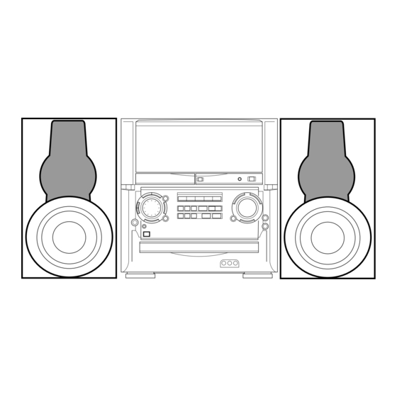
SERVICE MANUAL
COMPACT DISC STEREO
SYSTEM
SYSTEM
XH-N5
• This Service Manual is the "Revision Publishing" and replaces "Simple Manual",
(S/M Code No. 09-99C-424-7T1).
• If requiring information about the CD mechanism, see Service Manual
of AZG-1, (S/M Code No. 09-001-335-3N6).
XH-N5
BASIC TAPE MECHANISM : 6ZM-1 AR3NM
BASIC CD MECHANISM : AZG-1 ZD8RNDM
CD
CASSEIVER
CX-AN5
S/M Code No. 09-003-424-7R1
LH
REMOTE
SPEAKER
CONTROLLER
RC-AAS02
SX-WAN5
Advertisement
Table of Contents

Related Manuals for Aiwa XH-N5


Summary of Contents for Aiwa XH-N5
- Page 1 XH-N5 SERVICE MANUAL COMPACT DISC STEREO BASIC TAPE MECHANISM : 6ZM-1 AR3NM SYSTEM BASIC CD MECHANISM : AZG-1 ZD8RNDM REMOTE SPEAKER SYSTEM CASSEIVER CONTROLLER RC-AAS02 XH-N5 CX-AN5 SX-WAN5 • This Service Manual is the "Revision Publishing" and replaces "Simple Manual", (S/M Code No.
-
Page 2: Table Of Contents
TABLE OF CONTENTS SPECIFICATIONS ..............................3 PROTECTION OF EYES FROM LASER BEAM DURING SERVICING ............4 NOTE ON BEFORE STARTING REPAIR ....................5 ~ 6 DISASSEMBLY INSTRUCTIONS ........................7 ~ 8 ELECTRICAL MAIN PARTS LIST ......................9 ~ 13 CHIP RESISTOR PART CODE ........................14 TRANSISTOR ILLUSTRATION .......................... -
Page 3: Specifications
SPECIFICATIONS Main unit CX-AN5 <Cassette deck section> <FM tuner section> Track format 4 tracks, 2 channels stereo Tuning range 87.5 MHz to 108 MHz Frequency response 50 Hz – 15000 Hz Usable sensitivity (IHF) 13.2 dBf Recording system AC bias Antenna terminals 75 ohms (unbalanced) Heads... -
Page 4: Protection Of Eyes From Laser Beam During Servicing
PROTECTION OF EYES FROM LASER BEAM DURING SERVICING This set employs laser. Therefore, be sure to follow carefully the CAUTION instructions below when servicing. Use of controls or adjustments or performance of procedures other than those specified herein may result in hazardous WARNING! radiation exposure. -
Page 5: Note On Before Starting Repair
NOTE ON BEFORE STARTING REPAIR 1. Forced discharge of electrolytic capacitor of power supply block When repair is going to be attempted in the set that uses relay circuit in the power supply block, electric potential is kept charged across the electrolytic capacitors (C101, 102) even though AC power cord is removed. - Page 6 In such a case, check also if the POWER AMPLIFIER circuit or power supply circuit has any abnormalities or not. 2-2. Regarding reset There are cases that the machine does not work correctly because the MICROCOMPUTER is not reset even though the AC power cord is re-inserted, or the software reset (pressing the STOP key + POWER key) is performed.
-
Page 7: Disassembly Instructions
DISASSEMBLY INSTRUCTIONS CD DISASSEMBLING PROCEDURE 1. Remove the 19 screws (Ax11, Bx8) and remove the CABI, STEEL. CABI, STEEL 2. Remove the 3 screws from the bottom of the unit. 3. Remove the 4 screws (Ex2, Fx2) from both sides. –... - Page 8 4. Remove the 20 screws (Cx18, Dx2) and remove the 7. Remove the CHAS, 3CD together with the AZG-1. CABI, REAR ASSY. CHAS, 3CD CABI, REAR ASSY 5. Remove the 6 FFCs from the CONNECT C.B. 8. Remove the 2 screws and remove the AZG-1 from the CHAS, 3CD.
-
Page 9: Electrical Main Parts List
ELECTRICAL MAIN PARTS LIST REF. NO. PART NO. KANRI DESCRIPTION REF. NO. PART NO. KANRI DESCRIPTION MAIN C.B 8A-MT4-601-010 C-IC,LC866560W-5P68 87-012-369-080 C-CAP,S 0.047-50F 87-017-888-080 IC,NJM4558MD 87-012-369-080 C-CAP,S 0.047-50F 87-A20-914-010 IC,SPS-442-1-F 87-012-368-080 C-CAP,S 0.1-50 F 87-A21-021-040 C-IC,BU2099FV 87-012-368-080 C-CAP,S 0.1-50 F 87-A21-398-010 IC,STK490-110 87-012-368-080... - Page 10 REF. NO. PART NO. KANRI DESCRIPTION REF. NO. PART NO. KANRI DESCRIPTION C356 87-010-260-080 CAP, ELECT 47-25V C703 87-010-319-080 C-CAP,S 56P-50 CH C357 87-010-197-080 CAP, CHIP 0.01 DM C704 87-010-319-080 C-CAP,S 56P-50 CH C358 87-010-183-080 C-CAP,S 2700P-50 B C705 87-012-393-080 C-CAP,S 0.22-16 R K C359 87-010-183-080...
- Page 11 REF. NO. PART NO. KANRI DESCRIPTION REF. NO. PART NO. KANRI DESCRIPTION C122 87-010-408-040 CAP,E 47-50 M CN208 87-099-564-010 CONN,4P TUC-P4P-B1 C123 87-010-196-080 CHIP CAPACITOR,0.1-25 CN302 87-A60-163-010 CONN,15P H FE C125 87-010-196-080 CHIP CAPACITOR,0.1-25 CN303 87-A60-619-010 CONN,2P V 2MM JMT C126 87-010-196-080 CHIP CAPACITOR,0.1-25...
- Page 12 REF. NO. PART NO. KANRI DESCRIPTION REF. NO. PART NO. KANRI DESCRIPTION C133 87-010-197-080 CAP, CHIP 0.01 DM C951 87-010-196-080 CHIP CAPACITOR,0.1-25 C209 87-010-405-080 CAP, ELECT 10-50V C952 87-010-196-080 CHIP CAPACITOR,0.1-25 C210 87-010-405-080 CAP, ELECT 10-50V C953 87-010-188-080 CAP,CHIP 6800P C211 87-010-186-080 C-CAP,S 4700P-50 K B...
- Page 13 REF. NO. PART NO. KANRI DESCRIPTION REF. NO. PART NO. KANRI DESCRIPTION 87-026-682-080 PROTECTOR,10A 491 SERIES 60V C773 87-010-196-020 CHIP CAPACITOR,0.1-25 87-026-682-080 PROTECTOR,10A 491 SERIES 60V C774 87-010-263-080 CAP,ELECT 100-10V 87-026-682-080 PROTECTOR,10A 491 SERIES 60V C775 87-010-404-080 CAP,ELECT 4.7-50V 8A-MT4-621-010 PT,AMT-4 LH C776 87-012-286-020...
-
Page 14: Chip Resistor Part Code
TRANSISTOR ILLUSTRATION E C B E C B B C E G D S CC5551 DTC114ES FN1016 2SK3053 CSA1585 KTC3199 FP1016 CSC4115 CSD655 KTA1266 KTC3198 G D S 2SA1235 KTA1298 2SK2158 2SK2937 2SC3052 RT1N141C 2SC3326 RT1P141C CMBT5401 RT1P144C CMBT5551 RT1P441C DTA123EKA RT1N144C CHIP RESISTOR PART CODE... -
Page 15: Fl (Bj741Gk) Grid Assignment / Anode Connection
FL (BJ741GK) GRID ASSIGNMENT / ANODE CONNECTION GRID ASSIGNMENT – 15 –... - Page 16 ANODE CONNECTION – 16 –...
-
Page 17: Wiring - 1 (Main)
WIRING - 1 (MAIN) – 17 –... -
Page 18: Schematic Diagram - 1 (Main 1 / 2 : Function / Dsp / Echo / Connect1 / 3)
SCHEMATIC DIAGRAM – 1 (MAIN 1 / 2 : FUNCTION / BBE / DSP / ECHO / CONNECT1/3) – 18 –... -
Page 19: Schematic Diagram - 2 (Main 2 / 2 : Deck)
SCHEMATIC DIAGRAM – 2 (MAIN 2 / 2 : DECK) – 19 –... -
Page 20: Wiring - 2 (Front / Connect)
WIRING - 2 (FRONT / CONNECT) – 20 –... -
Page 21: Schematic Diagram - 3 (Front / Connect2 / 3 / Deck / Deck Motor)
SCHEMATIC DIAGRAM – 3 (FRONT / DECK / DECK MOTOR / CONNECT2/3) – 21 –... -
Page 22: Wiring - 3 (Operate / Key / Mic / Led-A ~ D)
WIRING - 3 (OPERATE / KEY / MIC / LED-A / LED-B / LED-C / LED-D) – 22–... -
Page 23: Schematic Diagram - 4 (Operate / Key / Mic / Led-A ~ D)
SCHEMATIC DIAGRAM – 4 (OPERATE / KEY / MIC / LED-A / LED-B / LED-C / LED-D) – 23 –... -
Page 24: Wiring - 4 (Amp)
WIRING - 4 (AMP) – 24–... -
Page 25: Schematic Diagram - 5 (Amp)
SCHEMATIC DIAGRAM – 5 (AMP) AMP C.B – 25 –... -
Page 26: Wiring - 5 (Video I/O / Video Jack / Video-3)
WIRING - 5 (VIDEO I/O / VIDEO JACK / VIDEO-3) – 26–... -
Page 27: Schematic Diagram - 6 (Video I/O / Video Jack / Video-3 / Connect 3/3)
SCHEMATIC DIAGRAM – 6 (VIDEO I/O / VIDEO JACK / VIDEO-3 / CONNECT 3/3) – 27 –... -
Page 28: Schematic Diagram - 7 (Tuner)
SCHEMATIC DIAGRAM – 7 (TUNER) – 29 –... -
Page 29: Wiring - 7 (Pt)
WIRING - 7 (PT / VOLTAGE SEL SW) – 30–... -
Page 30: Schematic Diagram - 8 (Pt)
SCHEMATIC DIAGRAM – 8 (PT / VOLTAGE SEL SW) – 31 –... -
Page 31: Wiring - 8 (Deck / Deck Motor / Head)
WIRING - 8 (DECK / DECK MOTOR / HEAD) – 32 –... -
Page 32: Ic Block Diagram
IC BLOCK DIAGRAM IC, BU4052BCF IC, BA7625 – 33 –... - Page 33 IC, BU4094BCF IC, BA7762AFS – 34 –...
- Page 34 IC, M62445AFP IC, SPS-442-1-F – 35 –...
- Page 35 IC, BA3880FS IC, LC72131D – 36 –...
- Page 36 IC, BA3835F IC, LA1837NL – 37 –...
- Page 37 IC, BU2099FV IC, BU9262AFS – 38 –...
-
Page 38: Ic Description
IC DESCRIPTION IC, LC866560W-5P68 Pin Name Description Pin No. M-CLK Clock output for MAIN, FRONT IC. M-DATA Data output for MAIN, FRONT IC. M-STB Strobe output for MAIN IC. PLL-CE PLL chip enable output. SR-STB Shift register strobe output. M-SR, STB Video switch and shift register strobe output. - Page 39 Pin Name Description Pin No. P27/DNR FL segment output P27 / Dolby Noise Reduction diode detect (Not used). P26/CST2 FL segment output P26 / DECK2 cassette detect switch data input. P25/REB FL segment output P25 / DECK2 side-B record OK switch data input. P24/CAM2 FL segment output P24 / DECK2 CAM switch data input.
-
Page 40: Adjustment -
ADJUSTMENT<TUNER / DECK / FRONT> MAIN C.B SFR352 L351 SFR351 L301 TP3(LCH) (GND) L302 TP4(RCH) IC303 IC601 TP2(RCH) TP1(LCH) (GND) R DECK C.B DECK R / P / E HEAD CON1 SFR1 FRONT C.B FL101 IC601 TP11(GND) C101 TP10(K-SCAN) L101 –... - Page 41 < DECK SECTION > < FRONT SECTION > µ 1. Tape Speed Adjustment -con Clock Adjustment Settings : • Test tape : TTA–100 Settings : • Test point : TP10 (K-SCAN) • Test point : TP3 (Lch), TP4 (Rch) TP11 (GND) •...
- Page 42 TUNER C.B CN701 (LCH) (GND) (RCH) TP3(DC) TP4(DC) L981 TP2(CLK) IC771 L771 L772 FFE801 TP1(VT) TP5(STOP) < TUNER SECTION > 7. DC Balance / Mono Distortion Adjustment 1. Clock Frequency Check Settings : • Test point : TP3,TP4 (DC balance) Settings : •...
-
Page 43: Mechanical Exploded View 1 / 1
MECHANICAL EXPLODED VIEW 1 / 1 P.C.B HT-SINK 6ZM-1 P.C.B P.C.B P.C.B P.C.B P.C.B VOL,SELECTOR AZG-1 ASSY P.C.B P.C.B P.C.B P.C.B P.C.B P.C.B CHAS,3CD – 44 –... -
Page 44: Mechanical Parts List 1 / 1
42 88-NF9-210-010 BUSHING,CORD-E 3 8A-MT4-023-010 WINDOW,AMP(4 LH) 43 87-A90-796-010 FAN,F614R-12MC-15-300MM 4 8A-MT4-010-010 PLATE,FL 44 8A-MTM-052-010 HLDR,FAN 5 87-B00-002-010 BADGE,AIWA 30 ABS SIL 45 88-MA1-208-110 JOINT,CABI 6 8A-MTM-042-010 PANEL,WINDOW 46 8A-MT4-002-010 CABI,REAR LH 7 8A-MT4-001-010 CABI,FR 47 8A-MTM-218-010 COVER,VOLTAGE 8 8A-MTM-011-010... -
Page 45: Tape Mechanism Parts List 1 / 2 <6Zl-1 A1
TAPE MECHANISM PARTS LIST 1 / 2 < 6ZL-1 A1 > BASE,MECHA P.C.B 6ZM-4 R3 – 46 –... - Page 46 TAPE MECHANISM PARTS LIST 1 / 2 < 6ZL-1 A1 > REF. NO. PART NO. KANRI DESCRIPTION 1 86-ZL1-203-010 TRAY,CAS 2 86-ZL1-204-010 LEVER,SLIDE L 3 86-ZL1-205-010 LEVER,SLIDE R 4 86-ZL1-202-010 FRAME,CAS 5 86-ZL1-209-010 LEVER,LOCK 6 86-ZL1-214-010 SPR-P,CAS 7 86-ZL1-211-010 ARM,CLAMP 8 86-ZL1-206-010 GEAR,TRAY 9 86-ZL1-213-010...
-
Page 47: Tape Mechanism Exploded View 2 / 2 <6Zm-4 R3
TAPE MECHANISM EXPLODED VIEW 2 / 2 < 6ZM-4 R3 > DECK C.B SOL2 CUSH-G DIA 3.7-9-3.2 SHAFT,REEL RELAY C.B PLATE, SHLD HLDR WIRE 3 SH,1.75-3.6 -0.5 SLT SH,1.63-3.2 -0.5 SLT – 48 –... -
Page 48: Tape Mechanism Parts List 2 / 2 <6Zm-4 R3
TAPE MECHANISM PARTS LIST 2 / 2 < 6ZM-4 R3 > REF. NO. PART NO. KANRI DESCRIPTION REF. NO. PART NO. KANRI DESCRIPTION 1 86-ZM1-218-010 CHAS ASSY,R 2 82-ZM1-258-110 SPR-T,PINCH L 36 82-ZM1-239-010 CAPSTAN,2.2-41.7 3 86-ZM4-202-019 LVR ASSY,PINCH L3 37 82-ZM1-223-010 GEAR,PLAY 4 82-ZM1-333-010 PLATE,LINK2... -
Page 49: Speaker Disassembly Instructions
SPEAKER DISASSEMBLY INSTRUCTIONS Type.1 Type.4 Insert a flat-bladed screwdriver into the position indicated by the TOOLS arrows and remove the panel. Remove the screws of each speaker 1 Plastic head hammer unit and then remove the speaker units. 2 (() flat head screwdriver 3 Cut chisel How to Remove the PANEL, FR Type.2... -
Page 50: Speaker Parts List
SPEAKER PARTS LIST SX-WAN5 (YLSL) REF. NO. PART NO. KANRI DESCRIPTION 1 8A-MS4-001-010 PANEL,FR 2 8A-MS4-003-010 PANEL,DUCT 3 8A-MS4-008-010 GRILLE,FRAME ASSY 4 8A-MS4-004-010 PANEL,RING 5 8A-MS4-011-010 PROTECTOR,TWA 6 8A-MS1-602-010 SPKR,W 200 7 8A-MS4-603-010 SPKR,M 120 8 88-NS3-605-010 9 88-MS1-610-010 CORD,SPKR 10 88-NS5-611-010 CORD,SPKR B/L 11 88-NS5-605-010... - Page 51 2–11, IKENOHATA 1–CHOME, TAITO-KU, TOKYO 110, JAPAN TEL:03 (3827) 3111 9820527 0251431 Printed in Singapore...
Need help?
Do you have a question about the XH-N5 and is the answer not in the manual?
Questions and answers