Table of Contents
Advertisement
PARTS LIST / TECHNICAL GUIDE
ANALOGUE SOLAR Cal. V172A/V174A
Item
V172A
(hour, minute and small
second hands)
Motion of the second hand
Driving system
Additional function
Normal position
Crown operation
1st click position
2nd click position
Loss/Gain
Regulation system
Gate time for rate measurement
Current consumption
Coil resistance
Power generator
Rechargeable battery
Power
supply
Operating voltage range
Power reserve
Number of jewels
Cal. No.
V174A
3 hands
(hour, minute and small second
hands), 24-hour indicator
One-second intervals
Stepping motor 4 pieces
Energy depletion forewarning function (The second hand moves at two-
second intervals.)
Overcharge prevention function
Electronic circuit reset function
Second hand stop function
Date calendar
Instant setting device for date calendar
System reset function
Stopwatch function..........60-minute stopwatch in 1/5-second increments
Stopwatch
Date setting(counter clockwise), Time setting of alarm
Time setting, System reset, Setting "0" of stopwatch hand
Monthly rate:less than 15 seconds (worn on the wrist at temperature range
between 5 to 35 degrees Centigrade)
Nil
Use 10-second gate
Movement: less than 0.80 μA
4002 541
(COIL BLOCK) (COIL BLOCK FOR STOPWATCH SECOND)
4002 542
(COIL BLOCK FOR STOPWATCH MINUTE) (COIL BLOCK FOR ALARM)
Solar power generation system
MT920 Manganese titanium lithium rechargeable battery
0.90V - 2.10V
From full charge to stoppage: Approximately 6 months
Nil
V172A/V174A
Diameter:
Outside 27.6 mm
Casing 27.0 mm
Height:
4.4 mm
(Auto stop measuring at 60 minutes)
Accumulated elapsed time measurement
Split time measurement
Single-time alarm function
Stopwatch hand position adjustment
Circuit block: less than 0.40 μA
1.90 - 2.30 kΩ
1.75 - 2.15 kΩ
1/24
Advertisement
Table of Contents

Subscribe to Our Youtube Channel
Related Manuals for Seiko V172A


Summary of Contents for Seiko V172A
- Page 1 PARTS LIST / TECHNICAL GUIDE ANALOGUE SOLAR Cal. V172A/V174A [SPECIFICATIONS] Cal. No. V172A/V174A Item V172A V174A Diameter: Outside 27.6 mm 3 hands 3 hands Casing 27.0 mm (hour, minute and small second (hour, minute and small hands), 24-hour indicator Height: 4.4 mm...
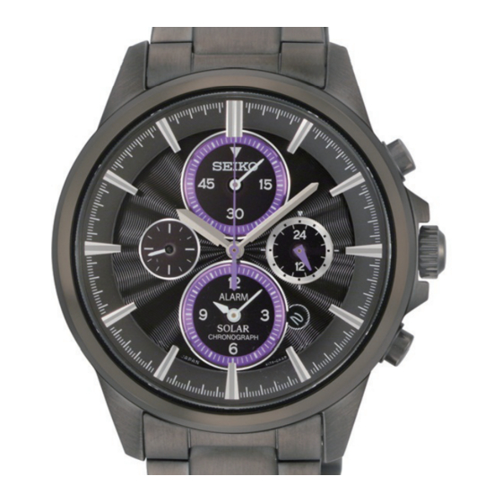
- Page 2 Cal. V172A/V174A SPECIFICATIONS FEATURES The Cal. V172A/V174A are analogue chronograph watches with a solar power generation system. l Solar power generation system The watch operates while charging electricity by converting light received on the dial to electrical energy. It lasts for 6 months after full charge.
- Page 3 PARTS LIST Cal. V172A/V174A Order of disassembly: 1 1 Order of assembly: Lubricating: Types of oil Oil quantity AO-3 Normal quantity AO-2 PIEZOELEcTRIc ELEMENT 4589 801 1 HOUR, MINUTE AND SMALL SEcOND HANDS, 24-HOUR HAND (V174A) cASE bAcK cASE bAcK GASKET...
- Page 4 PARTS LIST Cal. V172A/V174A 7 DATE DIAL GUARD SCREW (2PCS.) 0012 354 8 DATE DIAL GUARD 0808 525 9 DATE DIAL 0878 *** 10 DATE DRIVING WHEEL 11 GUIDE PLATE FOR DATE 0802 582 DIAL SCREW 0012 354 12 GUIDE PLATE FOR DATE DIAL...
- Page 5 PARTS LIST Cal. V172A/V174A 23 RECHARGEABLE BATTERY GUARD SCREW (3PCS.) 0022 230 24 RECHARGEABLE BATTERY GUARD 4225 616 (V172A) 4225 644 (V174A) 25 RECHARGEABLE BATTERY BLOCK 3023 24H 26 CIRCUIT BLOCK COVER SCREW (3PCS.) 0022 459 27 CIRCUIT BLOCK COVER...
- Page 6 PARTS LIST Cal. V172A/V174A 32 PIN FOR TRAIN WHEEL BRIDGE 0027 974 33 TRAIN WHEEL BRIDGE 0125 516 34 1/5-SECOND COUNTING WHEEL 0888 501 35 SMALL SECOND WHEEL 0240 511 36 FORTH WHEEL AND PINION 0241 583 37 THIRD WHEEL AND PINION...
- Page 7 PARTS LIST Cal. V172A/V174A 47 COIL BLOCK FOR ALARM 48 COIL BLOCK 4002 542 4002 541 49 COIL BLOCK FOR CHRONOGRAPH 1/5-SECOND 4002 541 50 COIL BLOCK FOR CHRONOGRAPH 51 SWITCH LEVER A MINUTE 4002 542 4450 703 53 ROTOR...
- Page 8 How to find the correct parts, if not determined by 4 digit caliber number Following parts are determined based on the design of watches, such as hands height, dial color, and design of cases. Please refer to the SEIKO WATCH PARTS CATALOGUE in order to choose the corresponding parts.
- Page 9 PARTS LIST Cal. V172A/V174A l Tools and consumables required for disassembling/reassembling • Movement holder UNIVERSAL MOVEMENT HOLDER (S-682) • Watch oils SEIKO watch oils (AO-3 and AO-2) and SEIKO watch grease S-6 AO-2 AO-3 9/24...
- Page 10 Cal. V172A/V174A TECHNICAL GUIDE REMARKS ON DISASSEMBLING AND REASSEMBLING HANDS • How to install * Match the polarity of the ROTORs for STOPWATCH and ALARM, and then install the hands. Check that the voltage of rechargeable battery exceeds 1.2 V and the watch is working.
- Page 11 TECHNICAL GUIDE Cal. V172A/V174A SPACER FOR SOLAR CELL • How to install Set the notched portions of the SPACER FOR SOLAR CELL to the guide posts (5 posts) of the HOLDING RING FOR DIAL, and check that the dial is fixed in position.
- Page 12 Cal. V172A/V174A TECHNICAL GUIDE • Disassembling and Reassembling of SOLAR CELL * Do not apply excessive force to the SOLAR CELL. <Disassembling> As there are 2 connection parts of the HOLDING RING FOR DIAL, release them side by side. <Assembling> Set the SOLAR CELL to 3 guide posts, and assemble it to the HOLDING RING FOR DIAL by expanding the hooking portion as shown in the illustlation.
- Page 13 TECHNICAL GUIDE Cal. V172A/V174A ㉔ RECHARGEABLE BATTERY GUARD • Assembling Set the RECHARGEABLE BATTERY GUARD to the guide posts (2 posts), and then tighten the rechargeable battery guard screws (3 pcs.). ScREW GUIDE POST ScREW GUIDE POST ScREW 13/25...
- Page 14 Cal. V172A/V174A TECHNICAL GUIDE ㉕ RECHARGEABLE BATTERY BLOCK • Assembling Set the notched portion of the RECHARGEABLE BATTERY BLOCK to the guide post, and check that the hooking portion of the RECHARGEABLE BATTERY BLOCK touches the (-) output terminal of the CIRCUIT BLOCK.
- Page 15 TECHNICAL GUIDE Cal. V172A/V174A ㉗ CIRCUIT BLOCK COVER • Disassembling 1. Loosen the 3 CIRCUIT BLOCK COVER SCREWs. 2. Release the 4 hooking portions of the CIRCUIT BLOCK COVER (indicated by the arrows in the illustration below.) • Assembling 1. Have the four hooking portions of the CIRCUIT BLOCK COVER (indicated by the arrows in the illustration below) catch the movement securely.
- Page 16 Cal. V172A/V174A TECHNICAL GUIDE ㉙ SECOND HOLD SPRING • Reassembly Slide a part of the SECOND HOLD SPRING under the TRAIN WHEEL BRIDGE. ㉚ CIRCUIT BLOCK a • Disassembling e Taking care not to damage the CIRCUIT BLOCK, remove it from the posts of the TRAIN WHEEL BRIDGE and the screw pins of the MAIN PLATE (refer to a, b, c, d and e in the illustration).
- Page 17 TECHNICAL GUIDE Cal. V172A/V174A ㉜ PIN FOR TRAIN WHEEL BRIDGE • Disassembling Turn the PIN FOR TRAIN WHEEL BRIDGE counter clockwise by 90 degrees, and loosen it. • Reassembling Set the PIN FOR TRAIN WHEEL BRIDGE as shown in the illustration, and tighten it by turning clockwise by 90 degrees.
- Page 18 Cal. V172A/V174A TECHNICAL GUIDE ● How to identify the gear train parts 46 MINUTE WHEEL FOR 45 CENTER WHEEL 44 INTERMEDIATE 52 ROTOR FOR ALARM ALARM FOR ALARM ALARM WHEEL 4146 710 0261 582 0902 502 0950 590 43 MINUTE WHEEL...
- Page 19 TECHNICAL GUIDE Cal. V172A/V174A How to lubricate ● SWITCH LEVER A SETTING LEVER YOKE TRAIN WHEEL SETTING LEVER WINDING STEM AO 3 S−6 CENTER WHEEL AND PINION MAIN PLATE AO2 AO3 19/25...
- Page 20 4) Touch the AC terminal of the CIRCUIT BLOCK and the switch spring with the tweezers to reset the circuit as illustrated. * When measuring the current consumption using the SEIKO digital multi-tester (S-860), use the range of 40 μA of SUPPLY V (=1.55 V) & GATE TIME (2S).
- Page 21 1) Connect each probe to the appropriate (-) and (+) input terminal of ㉚ CIRCUIT BLOCK (please refer to the "Structure of the CIRCUIT BLOCK" below). * When measuring the current consumption using the SEIKO digital multi-tester (S-860), use the range of 40 μA of SUPPLY V (=1.55 V) & GATE TIME (2S).
- Page 22 2) Pull out the crown to the 2nd click in order to reset the circuit. 3) Connect the (-) probe and (+) probe as illustrated. * When measuring the voltage using the SEIKO digital multi-tester (S-860), use the range of V. 4) Expose the watch to the light of a fluorescent lamp (use the one with 15 to 20 watts) at a distance of 5-10 cm while connecting the probes to the watch.
- Page 23 1) Set the SOLAR CELL to the HOLDING RING FOR DIAL. 2) Connect the tester as the below illustration. * When measuring the voltage using the SEIKO digital multi-tester (S-860), use the range of V. 2) Expose the SOLAR CELL to the light of a fluorescent lamp (use the one with 15 to 20 watts) at a distance of 5-10 cm while connecting the probes to the solar cell unit (Fig.
- Page 24 Refer to the table below for the criteria of the inspection. 5-10 cm Table - criteria recharging function Cal. V172A/V174A Results after recharging and criteria for checking the function The voltage The battery needs to be inspected and...
- Page 25 TECHNICAL GUIDE Cal. V172A/V174A TROUBLESHOOTING IF THE WATCH DOES NOT MOVE PROPERLY AFTER RECHARGING. Without recharging, the power stored in a solar watch begins to decline. The second hand starts moving at 2-second intervals indicating a diminished power reserve and eventually stops completely unless the watch is recharged.
Need help?
Do you have a question about the V172A and is the answer not in the manual?
Questions and answers