Table of Contents
Advertisement
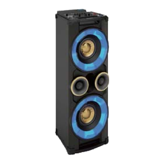
Mini Hi-Fi System
TABLE OF CONTENTS
Technical specification ...........................................................1-14
Safety Instruction......................................................................2-1
Set Block diagram ....................................................................3-1
Set Wiring diagram ...................................................................4-1
Disassembly diagram ...............................................................5-1
Main and jack board
AMP
MCU
Mechanical Exploded view.......................................................9-1
©
Copyright 2013 Philips Consumer Electronics B.V. Eindhoven, The Netherlands
All rights reserved. No part of this publication may be reproduced, stored in a retrieval system or
transmitted, in any form or by any means, electronic, mechanical, photocopying, or otherwise without
the prior permission of Philips.
Published by LX 1
334
Service Audio
Version 1.0
Circuit diagram.......................................................6-1...6-2...6-3
Layout diagram................................................................6-4..6-5
board
Circuit diagram........................................................................7-1
Layout diagram.......................................................................7-2
board and CD board
Circuit diagram...............................................................8-1...8-2
Layout diagram..............................................................8-3...8-4
Printed in The Netherlands
Chapter
Subject to modi fi cation
NTRX500/
all
3140 038 60830
Advertisement
Table of Contents

Related Manuals for Philips NTRX500


Summary of Contents for Philips NTRX500
- Page 1 Mechanical Exploded view............9-1 © Copyright 2013 Philips Consumer Electronics B.V. Eindhoven, The Netherlands All rights reserved. No part of this publication may be reproduced, stored in a retrieval system or transmitted, in any form or by any means, electronic, mechanical, photocopying, or otherwise without the prior permission of Philips.
- Page 2 Main Board Tuner Board MIC Board BT Board Jack Board CD Board Amp Board SMPS Board VERSION VARIATION Type /Versions: NTRX500 x/78 Service policy Board in used: MAIN BOARD VOLUME BOARD AMP BOARD DJ EFFECT BOARD JACK BOARD TUNER BOARD...
- Page 3 NX5 NX7 ALL SH190 Contact List Descrpitopn Page...
- Page 4 Tested according to General Test Instruction refer to PHILIPS standary ( UAN -D1591 ) Measured according to PHILIPS standary ( UAN - L1059 ) unless other wise stated All not mentioned date, please refer to PHILIPS standary ( XUW - 0010 - JUNE 2001 ) DERIVED...
- Page 5 TECHNIAL DESCRIPTION Total power 500W FOR NX5 1000W FOR NX7 ), FOUR INPUT SOURCE, ( Digital Sound Control ). IS ( Incredible Sound ) GENERAL PART OUTPUT stage Protection : Yes Temperature : Yes. Shorcircuit : Yes LoudSpeaker D.C. Protection : Yes.
- Page 6 AUDIO SIGNAL PROCESSING MP3-USB Mini Hi Fi System with Digital Tuner ,Class AB Power Amplifier DSC ( Digital Sound Control ) Select AUX as input source with the following set conditions: Inject sine wave 2V at 1 KHz to L/R channels of AUX-IN socket. Set DSC to JAZZ(Flat) mode and switch off DBB.
- Page 7 AUDIO SIGNAL PROCESSING MP3 - USB Mini Hi Fi System with Digital Tuner , 1CDCfor NX5 NX7 ALL IS ( Incredible Sound ) Select AUX as input source. Inject sine wave 2V at 1kHz to AUX-IN socket, one channel at a time (input level 500mV for /37,2V for /55 ). Set DSC to JAZZ ( Flat ) mode and switch of DBB, OSM &...
- Page 8 TECHNIAL DESCRIPTION AUX modle GENERAL PART Description Specification Output power = , 1 Khz ) 125W± 1 Db(NX5) 250W± 1 Db(NX7) Channel Unbalance < = +/- 3 dB THD + Noise ( 0dB, 1Khz ) <=2% Channel Crosstalk ( ( 0dB, 1 KHz ) >= 40dB ( 0 dB, 10 KHz ) >= 40dB...
- Page 9 TECHNIAL DESCRIPTION SOFTWARE IMPLEMENTED CLOCK / TIMER FUNCTION WITHOUT 32.768KHZ QUARTZ OSCILLATOR. GENERAL PART Timer Setting Clock and Timer Timer Wakeup Mode CD USB or Tuner Remarks Time Setting 12hr for /37 version, 24hrs for other version. Volume at Wakeup Last Setting Nom : 1 sec/day Limit...
- Page 10 1-10 TECHNIAL DESCRIPTION See also SH 190 USB Audio Module (300605) Measurment are directly done at the coonector on the board GENERAL PART Measurement are directly done at the connector on CDC board Description Specification Output Resistance < = 1.5 kOhm Output Voltage RL = 33 k ohm dB, 1 Khz Channel Unbalance <...
- Page 11 1-11 TECHNIAL DESCRIPTION GENERAL PART WAVE RANGE TOLERANCE TUNING GRID FM( 55/37 ) 87.5 - 108.00 MHz QUARTZ PRECISION 100 kHz FM( 12 ) 87.5 - 108.00 MHz 50KHZ AM (55/37) 530 - 1700 QUARTZ PRECISION 10 kHz AM (12) 531 - 1602 QUARTZ PRECISION 9 kHz...
- Page 12 1-12 TECHNIAL DESCRIPTION Bluetooth Function GENERAL PART Bluetooth Version : Ver2.1 + EDR Receive A2DP: Transmit A2DP: Remote Controlled Receive HSP Noise Reduction System INDICATORS Bluetooth Flashing Display ELECTRICAL DATA Bluetooth at Module level: Mobile Phone Unit Frequency Response 125-16khz S/N (Unweighted) S/N (A-weighted) Level Diff...
- Page 13 1-13 TECHNIAL DESCRIPTION CD + MP3 - Part Specifications (CD MECHAISM DA11VF OF SANYO ) 1DISC for NX5 NX7 ALL Input Output Motor Logic control Active components SA5888 BU9543 Signal processsing D/A converter HF-preamplifier Servo processor Active components BU9543 BU9543 DA23SR AUDIO part: Measurement with Audio Signals Disc TCD-781 on spkeakers or Headphone socket with nom.load Extern...
- Page 14 1-14 VERSION OVERVIEW (NX5 NX7) ALL APPROBATION TUNER AC SUPPLY DEST SURR MAINS SAFETY Wave RANGE GRID AERIAL SOCKET AERIAL SUPPLIED SOC. CORD . SPK. VOLTAGE EN60065 110-127V FM 87.5-108MHz MW 50kHz CLASS II 75 Ohm Coaxial 75 Ohm Pigtail Switched /55 /98 CISPR 13...
-
Page 15: Safety Instruction
2.Safety instruction 1. General safety 2.Laser safety Safety regulations require that during a repair: This unit employs a laser. Only qualified service personnel . Connect the unit to the mains via an isolation transformer. may remove the cover, or attempt to service this device . - Page 16 BLOCK DIAGRAM...
- Page 17 WIRING DIAGRAM...
- Page 18 OUTER 1) Remove 46 screws A/B/C/D/E/F/G as indicated to loosen the top/front/bottom plate. Dismantling of the CD part and PCB Board 1) Remove 8 screws H&I as indicated to loosen the CD part. 2) Remove 4 screws J as indicated to loosen the CD Board. 4) Remove 13 screws K and 8 screws L as indicated to loosen the Main Board.
- Page 19 CIRCUIT DIAGRAM - MAIN BOARD AND JACK BOARD...
- Page 22 PCB LAYOUT - MAIN BOARD...
- Page 23 PCB LAYOUT - JACK BOARD...
- Page 24 CIRCUIT DIAGRAM - AMP BOARD...
- Page 25 PCB LAYOUT - AMP BOARD...
- Page 26 CIRCUIT DIAGRAM - MCU BOARD AND CD BOARD...
- Page 27 CIRCUIT DIAGRAM - MCU BOARD AND CD BOARD...
- Page 28 PCB LAYOUT - MCU + CD BOARD...
- Page 29 PCB LAYOUT - MCU + CD BOARD...
- Page 30 EXPLODED VIEW...
Need help?
Do you have a question about the NTRX500 and is the answer not in the manual?
Questions and answers
where can i get my nx7 skp sys fixed
looking for component list for philips nx7 speaker sys