
Subscribe to Our Youtube Channel
Related Manuals for Buderus Logamatic EMS


Summary of Contents for Buderus Logamatic EMS
- Page 1 Mounting and Service Room controller Instructions Logamatic EMS For trained and certified installers RC35 user interface Read carefully prior to installation and maintenance.
-
Page 2: Table Of Contents
Operating tips ............23 Logamatic EMS RC35 user interface - Subject to technical modifications. - Page 3 Notes ..............57 Logamatic EMS RC35 user interface - Subject to technical modifications.
-
Page 4: Explanation Of Symbols And Safety Instructions
They are separated by lines above and below the text. Additional symbols Symbol Explanation Sequence of steps Cross-reference to other points in this document or to other documents • Listing/list entry – Listing/list entry (2nd level) Tab. 1 Logamatic EMS RC35 user interface - Subject to technical modifications. - Page 5 Note on using this manual: Section 4.2 "Introduction to the Service menu" explains in detail the steps needed for programming all the settings in the Service menu. In the sections which come after it, programming is only exexplained in outline. Logamatic EMS RC35 user interface - Subject to technical modifications.
-
Page 6: Safety Instructions
The RC35 has no field serviceable parts inside. Attempt to open the housing will cause internal damage, render the device inoperable, and void the manufacturer's warranty. B In case of system irregularities please consult the 7 "Diagnosis" and 10 "Troubleshooting" sections of this manual. Logamatic EMS RC35 user interface - Subject to technical modifications. -
Page 7: Product Description
Product description Product description 2.1 Correct use The RC35 control unit is intended for the operation and control of Buderus heating systems in single and multi-family houses. The boiler must be equipped with EMS (energy management system). The user interface must not be used in conjunction with Logamatic 2000/4000 control units. -
Page 8: Technical Specifications
212 °F (100 °C) 0.677 77 °F (25 °C) 10.001 131 °F (55 °C) 2.989 86 °F (30 °C) 8.060 Ω Tab. 3 Resistances of the 10 k temperature sensors, for EMS only Logamatic EMS RC35 user interface - Subject to technical modifications. -
Page 9: Applicability Of These Instructions For Function Modules (Accessories)
• MM10 mixing module for controlling a 3-way mixing valve • WM10 low loss header module • Solar module and other EMS modules • Outdoor temperature sensor, separate room temperature sensor Logamatic EMS RC35 user interface - Subject to technical modifications. -
Page 10: Installation
(this requires an outdoor sensor). Alternatively, you could install an external room temperature sensor in the room with the greatest heating requirements (e.g. living room). Fig. 1 Minimum clearances for mounting in a reference room Logamatic EMS RC35 user interface - Subject to technical modifications. -
Page 11: Installation On Boiler
• As the only user interface in a heating system with two or more heating zones ( Fig. 2). Examples: radiant floor heating on one story, radiators in the other. Fig. 2 Options for a heating system with two heating zones Logamatic EMS RC35 user interface - Subject to technical modifications. -
Page 12: Installation And Connection
B If the RC35 is operated with an external room temperature sensor (optional), the factory-installed jumper on “EXT” must be removed and the external room temperature sensor must be connected there instead. Logamatic EMS RC35 user interface - Subject to technical modifications. -
Page 13: User Interface: Attaching Or Removing
1. Press the button underneath the mounting plate in the direction of the arrow. 2. At the same time pull the user interface forwards. 3. Remove the user interface by lifting upward. Logamatic EMS RC35 user interface - Subject to technical modifications. -
Page 14: Operating Basics
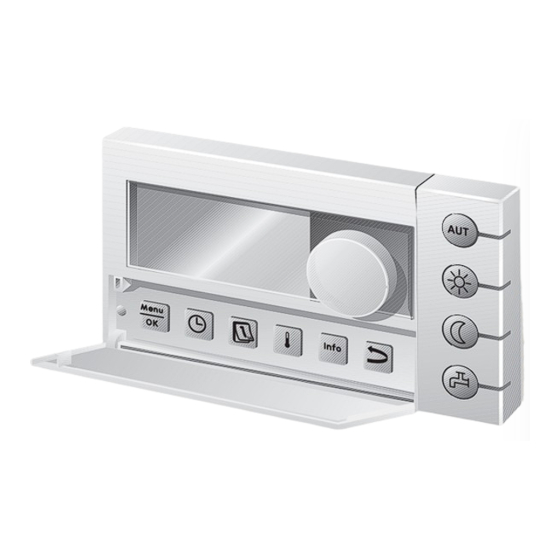
In Automatic mode, an additional LED lights up with the “AUT” LED to indicate which operating status is currently active (“day mode” or “night mode”). The “domestic hot water” LED can also be disabled. Logamatic EMS RC35 user interface - Subject to technical modifications. -
Page 15: Introduction To The Service Menu
Press to confirm the selection. SERVICE\SETTINGS system data The SERVICE\SETTINGS menu is opened. boiler data domestic hot water heating zone 1 Tab. 4 How to use the Service menu (example) Logamatic EMS RC35 user interface - Subject to technical modifications. - Page 16 To finish entering settings, shut the cover. The standard display re-appears. You can enter all settings in the SERVICE MENU using this procedure. Tab. 4 How to use the Service menu (example) Logamatic EMS RC35 user interface - Subject to technical modifications.
-
Page 17: Overview Of The Service Menu
Tab. 5 Service menu navigator 1) Subject to restrictions depending on which boiler is used. 2) Not possible or not available, depending on the boiler used. Logamatic EMS RC35 user interface - Subject to technical modifications. -
Page 18: Commissioning
Tab. 6 General commissioning If necessary, you can change the contrast on the display: B Hold down the buttons and turn the dial at the same time. Logamatic EMS RC35 user interface - Subject to technical modifications. -
Page 19: Checklist: Important Parameters For Commissioning
... DHW Priority heating zone x, page 30 ... program Standard program family heating zone x, (times) e.g. family, page 31 custom program Tab. 7 Checklist: important parameters for commissioning Logamatic EMS RC35 user interface - Subject to technical modifications. -
Page 20: Quick Commissioning (Quick Operation Menu)
1. Which heating system panel radiator, panel Heating characteristic does heating zone 1 convector, radiator curve ( page 33) have? floor Tab. 8 Quick operation menu navigator Logamatic EMS RC35 user interface - Subject to technical modifications. -
Page 21: Detailed Commissioning
B Explain to the customer how the device works and how to operate it. B Inform the customer of the settings chosen. We recommend giving these installation and servicing instructions to the customer so they can be kept close to the heating system. Logamatic EMS RC35 user interface - Subject to technical modifications. -
Page 22: Shut-Down/Switching Off
After switching the unit OFF or in the event of a power failure, the date and time are retained for up to 8 hours. All other settings are permanently memorized. Logamatic EMS RC35 user interface - Subject to technical modifications. -
Page 23: Operating Tips
12 noon to prevent pump damage. The mixing valves are then set to “OPEN” for 10 seconds and then to “CLOSE”. After 10 seconds, all pumps and mixing valves then return to their normal, regulated operation. 1) Room in which an RC35 is installed. Logamatic EMS RC35 user interface - Subject to technical modifications. -
Page 24: Entering System Settings (Service Menu - Settings)
Set the address on the dial on the zones are installed? MM10 mixing module (factory setting: HZ2). Has a solar module been yes, no installed? Tab. 9 Navigator for Service menu SETTINGS\SYSTEM Logamatic EMS RC35 user interface - Subject to technical modifications. -
Page 25: Type Of Building ("Damping" Of Outdoor Temperature)
Massive buildings with high heat storage capacity and high levels of insulation, e.g. poured concrete, heavy brick or heavy cinder block construction with excellent insulation. Tab. 10 Calculating the damping time constant Logamatic EMS RC35 user interface - Subject to technical modifications. -
Page 26: Minimum Outdoor Temperature
The value can be taken from the heat requirement calculation that should be done for every building, or from the climatic zone chart of your region. Logamatic EMS RC35 user interface - Subject to technical modifications. -
Page 27: Boiler Data
• 0: if a hydraulic low loss header has been installed • 1 – 8: see boiler documentation Tab. 11 Navigator for Service menu SETTINGS\BOILER 1) system-dependent Logamatic EMS RC35 user interface - Subject to technical modifications. -
Page 28: Heating Zone Data
(30 °C – 90 °C) (panel radiator, mode has been set to outdoor convector) reset ( page 33). 113 °F (45 °C) (floor) Tab. 12 Navigator for Service menu SETTINGS\HTG. ZONE 1 Logamatic EMS RC35 user interface - Subject to technical modifications. - Page 29 RC20 or RC35 has been room temperature assigned to the heating zone page 35). Tab. 12 Navigator for Service menu SETTINGS\HTG. ZONE 1 Logamatic EMS RC35 user interface - Subject to technical modifications.
- Page 30 (25 °C – 60 °C) temperature. For how many days 0 – 20 days 4 days should max. supply temp. be maintained? Tab. 12 Navigator for Service menu SETTINGS\HTG. ZONE 1 Logamatic EMS RC35 user interface - Subject to technical modifications.
- Page 31 34). vacation mode? Setting entered only if the reduc- tion mode for vacation has been set to Outdoor setback mode. Tab. 12 Navigator for Service menu SETTINGS\HTG. ZONE 1 Logamatic EMS RC35 user interface - Subject to technical modifications.
-
Page 32: Assignment Of User Interface/Remote Control Unit In The Software
(factory setting: 0 °F (0 °C)). This applies when the room temperature exceeds or falls below the target room temperature. If the maximum room influence parameter is set to 0, the heating characteristics will be controlled solely by outdoor temperature. Logamatic EMS RC35 user interface - Subject to technical modifications. -
Page 33: Characteristic Heating Curve
Fig. 6, right). This feature should be used if, for example, the room temperature measured with a thermometer differs from the set target value. Logamatic EMS RC35 user interface - Subject to technical modifications. -
Page 34: Reduction Modes (Night Setback)
This must be at least 2 °F (1 °C) lower than the daytime target room temperature. The heating characteristics will be calculated in accordance with this setting.This setting is recommended for radiant floor heating. Logamatic EMS RC35 user interface - Subject to technical modifications. -
Page 35: Frost Protection
(for example) could freeze even though the temperature in the reference room might be clearly above 41 °F (5 °C) due to external heat sources (fireplace etc.). Logamatic EMS RC35 user interface - Subject to technical modifications. - Page 36 If the outdoor temperature falls below the set value of 6 °F (–15 °C), heating switches from reduced operation to heating operation ( Fig. 7, [3]). This allows smaller heating surfaces to be utilized. Logamatic EMS RC35 user interface - Subject to technical modifications.
-
Page 37: Domestic Hot Water (Dhw)
Confirm changing the DHW yes, no Selecting “yes” takes you program. to the program for domestic hot water. Recirculation Is a recirculation pump yes, no installed? Tab. 14 Navigator for Service menu SETTINGS\DHW Logamatic EMS RC35 user interface - Subject to technical modifications. - Page 38 LED. Tab. 14 Navigator for Service menu SETTINGS\DHW 1) Depending on the boiler, a fixed temperature is defined and it cannot be changed. Logamatic EMS RC35 user interface - Subject to technical modifications.
-
Page 39: Solar Data
What is the minimum pump rating? 20 % – 100 % 30 % Tab. 15 Navigator for Service menu SETTINGS\SOLAR For explanations of the settings, see the documentation for the SM10 solar module. Logamatic EMS RC35 user interface - Subject to technical modifications. -
Page 40: Rc35 Calibration
Example: if the thermometer is showing a temperature 2 °F (1 °C) higher than the controls, enter “+2 °F (+1 °C)” as the calibration value. Logamatic EMS RC35 user interface - Subject to technical modifications. -
Page 41: Contact Data
Release the button: the modified character is saved. 2. Turn the dial counter-clockwise or clockwise to move the cursor. 3. To delete a character, enter a space. 4. Press to save your entries and leave the menu. Logamatic EMS RC35 user interface - Subject to technical modifications. -
Page 42: Diagnosis
Be mindful of the information which appears on the display when you switch to menus or when you enter settings. Press any of the buttons or turn the dial to confirm the information. Logamatic EMS RC35 user interface - Subject to technical modifications. -
Page 43: Monitor Value
1) The monitor values are displayed per boiler on an individual screen. By turning the dial, the monitor values for the next boiler are called up. Symbol present = corresponding function is active. Key to symbols Tab. 19, page 44. Logamatic EMS RC35 user interface - Subject to technical modifications. -
Page 44: Error Message
For a list of the locking and blocking faults, which vary depending on the boiler, see the installation and maintenance instructions of the boiler. B Turn the dial to show the next message. Logamatic EMS RC35 user interface - Subject to technical modifications. -
Page 45: Characteristic Heating Curve
You can use the INFO\VERSIONS menu to view the software versions for heating system components. B If the information cannot be displayed in one screen: turn the dial to INFO\VERSIONS display the next screen. RC35 1.02 UBA3.5 1.21 Logamatic EMS RC35 user interface - Subject to technical modifications. -
Page 46: Service
RESET service Confirm resetting no, yes If you select “yes” the the service servicing messages messages. will be reset. Observe information in display. Tab. 20 Navigator for the Servicing menu Logamatic EMS RC35 user interface - Subject to technical modifications. -
Page 47: Reset
When the button is released, the reset is carried out. During this process, a corresponding message appears, which disappears again automatically. B Once reset is complete: confirm by pressing any of the buttons. Logamatic EMS RC35 user interface - Subject to technical modifications. -
Page 48: Troubleshooting
Use only original Buderus parts. Losses caused by the use of parts not supplied by Buderus are excluded from the Buderus warranty. - Page 49 B Check that the DHW pump incorrectly connected DHW pump is or defective. working, e.g. by carrying out a function test. Tab. 21 Fault table Logamatic EMS RC35 user interface - Subject to technical modifications.
- Page 50 BC10 settings are no Contact problem on communi- longer accepted by RCxx BC10, or BC10 connection. cation with devices. faulty. B Replace BC10 if BC10 necessary. Tab. 21 Fault table Logamatic EMS RC35 user interface - Subject to technical modifications.
- Page 51 Temperature sensor mounted. amount. is defective. B Compare resistance values with the characteristic sensor curve. Tab. 21 Fault table Logamatic EMS RC35 user interface - Subject to technical modifications.
- Page 52 B Change to outdoor last values set on the HZx. although room temperature remote control. temperature controlled if needed. controlled is set. Tab. 21 Fault table Logamatic EMS RC35 user interface - Subject to technical modifications.
- Page 53 Tab. 21 Fault table System errors do not need resetting. Contact your local service contractor or your local Buderus office if you cannot remedy the fault yourself. Other faults are described in the technical documentation for the boiler. Logamatic EMS RC35 user interface - Subject to technical modifications.
-
Page 54: Service Menu Rc35
Service menu RC35 11 Service menu RC35 Logamatic EMS RC35 user interface - Subject to technical modifications. -
Page 55: Index
EMS bus, devices on ....23 Outdoor temperature, “damped” ..25 Errors, Service menu – Diagnosis ..44 Logamatic EMS RC35 user interface - Subject to technical modifications. - Page 56 Switching off ......22 System data, Service menu – Settings ..24 Logamatic EMS RC35 user interface - Subject to technical modifications.
-
Page 57: Notes
Notes Logamatic EMS RC35 user interface - Subject to technical modifications. - Page 58 Notes Logamatic EMS RC35 user interface - Subject to technical modifications.
- Page 59 Notes Logamatic EMS RC35 user interface - Subject to technical modifications.
Need help?
Do you have a question about the Logamatic EMS and is the answer not in the manual?
Questions and answers