Table of Contents
Advertisement
P/N 900463-01 Rev. A 01/2016
This appliance may be installed in an aftermarket permanently located, manufactured (mobile) home, where not
prohibited by local codes. This appliance is only for use with the type of gas indicated on the rating plate. This
appliance is not convertible for use with other gases.
WARNING: This appliance is for installation only in a solid-fuel burning masonry or UL127 factory-built
fi replace or in a listed ventless fi rebox enclosure. It is design-certifi ed for these installations in accordance
with ANSI Z21.11.2. Exception: DO NOT install this appliance in a factory-built fi replace that includes
instructions stating it has not been tested or should not be used with unvented gas logs.
This is an unvented gas-fi red heater. It uses air (oxygen) from the room in which it is installed. Provisions
for adequate combustion and ventilation air must be provided. Refer to Air for Combustion and Ventilation
section on Page 6 of this manual.
WARNING:
FIRE OR EXPLOSION HAZARD
Failure to follow safety warnings exactly could result in serious injury, death, or property damage.
- Do not store or use gasoline or other fl ammable vapors and liquids in the vicinity of this or any other appli-
ance.
- WHAT TO DO IF YOU SMELL GAS
• Do not try to light any appliance.
• Do not touch any electrical switch; do not use any phone in your building.
• Leave the building immediately.
• Immediately call your gas supplier from a neighbor's phone. Follow the gas supplier's instructions.
• If you cannot reach your gas supplier, call the fi re department.
- Installation and service must be performed by a qualifi ed installer, service agency or the gas supplier.
INSTALLER: Leave this manual with the appliance.
CONSUMER: Retain this manual for future reference.
Installation and Operation Instructions
Superior
Models
MNF24INM
PFS
MNF24IPM
®
US
For use with log sets
Report No. 10-87
®
Unvented (Vent-Free) Gas Log Heater
MNF30INM
MNF30IPM
LMF24GTA/B
LMF30GTA/B
LMF36GTA/B
P900463-01
MNF24INV
MNF30INV
MNF24IPV
MNF30IPV
LMF24MOA/B
LMF30MOA/B
LMF36MOA/B
Advertisement
Table of Contents

Related Manuals for Superior MNF24INM


Summary of Contents for Superior MNF24INM
- Page 1 Installation and Operation Instructions ® Superior Unvented (Vent-Free) Gas Log Heater P/N 900463-01 Rev. A 01/2016 Models MNF24INM MNF30INM MNF24INV MNF30INV MNF24IPM MNF30IPM MNF24IPV MNF30IPV ® For use with log sets Report No. 10-87 LMF24GTA/B LMF24MOA/B LMF30GTA/B LMF30MOA/B LMF36GTA/B LMF36MOA/B This appliance may be installed in an aftermarket permanently located, manufactured (mobile) home, where not prohibited by local codes.
-
Page 2: Table Of Contents
TABLE OF CONTENTS Safety ..............2 Cleaning and Maintenance ........ 30 Product Identifi cation ........... 5 Specifi cations ............ 31 Local Codes............5 Wiring Diagram ..........31 Optional Remote Control Accessories ....5 Troubleshooting ..........32 Unpacking............5 Parts ..............36 Product Features .......... - Page 3 SAFETY Continued WARNING: This product con- WARNING: Do not allow fans tains and/or generates chemicals to blow directly into the appliance. known to the state of California Avoid any drafts that alter burner to cause cancer or birth defects fl ame patterns. Ceiling fans can create drafts that alter burner fl...
- Page 4 SAFETY Continued 1. This appliance is only for use with the type 9. Before using furniture polish, wax, carpet of gas indicated on the rating plate. This ap- cleaner or similar products, turn appliance pliance is not convertible for use with other off.
-
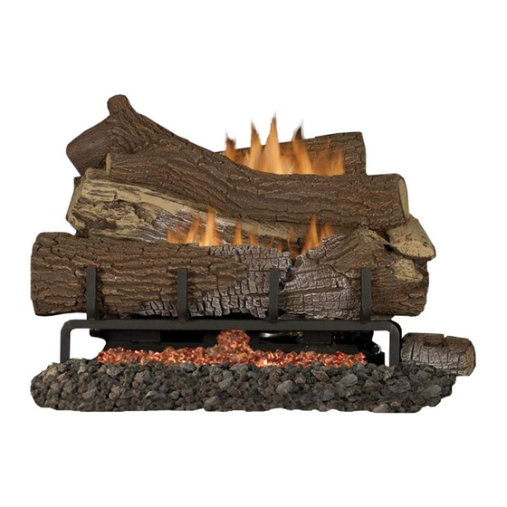
Page 5: Product Identifi Cation
PRODUCT IDENTIFICATION Left Side Right Side Chassis Control Knob Glowing Embers Flame Adjustment Knob Front Figure 1 - Product Identifi cation LOCAL CODES Install and use appliance with care. Follow all State of Massachusetts: The installa- local codes. In the absence of local codes, use tion must be made by a licensed plumber the latest edition of The National Fuel Gas or gas fitter in the Commonwealth of... -
Page 6: Product Features
PRODUCT FEATURES OPERATION SAFETY DEVICE This appliance is clean burning. It requires This appliance has a pilot with an Oxygen no outside venting. There is no heat loss out Depletion Sensing (ODS) safety shutoff a vent or up a chimney. Heat is generated by system. - Page 7 AIR FOR COMBUSTION AND VENTILATION Continued whether the space in which the heater is being Vent-free fi replace __________ Btu/Hr installed is confi ned or unconfi ned space. The Gas water heater* __________ Btu/Hr standard method defi nes a confi ned space as Gas furnace __________ Btu/Hr a space whose volume is less than 50 cubic...
-
Page 8: Installation
AIR FOR COMBUSTION AND VENTILATION Continued VENTILATION AIR Ventilation Air From Outdoors Provide extra fresh air by using ventilation Ventilation Air From Inside Building grills or ducts. You must provide two perma- This fresh air would come from an adjoining nent openings: one within 12"... - Page 9 INSTALLATION CHECK GAS TYPE Use the correct type of gas (natural or propane/ Continued LP). If your gas supply is not the correct gas type, do not install appliance. Call dealer where WARNING: Before installing you bought appliance for proper type appliance. in a solid fuel-burning fi...
- Page 10 INSTALLATION Continued NOTE: When installing your gas logs into Noncombustible Requirements for a manufactured fi rebox, follow fi rebox Material Distance Safe Installation manufacturer’s instructions for minimum clearances to combustible materials. 12" or more Noncombustible mate- B. Clearances from the top of the fi replace rial OK.
- Page 11 INSTALLATION Continued MANTEL CLEARANCES NOTICE: Surface temperatures In addition to meeting noncombustible mate- of adjacent walls and mantels be- rial clearances, you must also meet required come hot during operation. Walls clearances between fi replace opening and and mantels above the fi rebox mantel shelf.
- Page 12 INSTALLATION Continued INSTALLING DAMPER CLAMP Damper Clamp ACCESSORY FOR VENTED OPERATION Damper NOTE: When used as a vented appliance, appliance must be installed only in a solid- Damper fuel-burning fi replace with a working fl ue and Clamp constructed of noncombustible material. For Massachusetts Residents Only: Instal- lation of this gas log set as a vented appliance Damper...
- Page 13 INSTALLATION Continued Masonry Screw Installation Items Needed • hardware package (provided with appli- ance) • approved fl exible gas hose and fi ttings provided (if allowed by local codes) • sealant (resistant to propane/LP gas, not provided) • electric drill with 3/16” masonry drill bit NOTE: Install optional MRC Series receiver and hand-held remote control kit (see Ac- cessories, Page 41) before installing gas...
- Page 14 INSTALLATION Continued Installation Items Needed Apply pipe joint sealant lightly to male NPT Before installing appliance, make sure you threads. This will prevent excess sealant from have the items listed below. going into pipe. Excess sealant in pipe could result in clogged appliance valves. •...
- Page 15 INSTALLATION Continued We recommend that you install a sediment 3. Pressurize supply piping system by either opening propane/LP supply tank valve trap in supply line as shown in Figure 14, for propane/LP gas or opening main gas Page 14. Locate sediment trap where it is valve located on or near gas meter for within reach for cleaning.
- Page 16 INSTALLATION Continued Equipment Shutoff Valve Connect the wires to the valve from the switch assembly as shown in Figure 18. INSTALLING OPTIONAL REMOTE Gas Meter ACCESSORIES (REMOTE READY MODELS) Installing Remote Receiver Remote control accessories are available separately (see Accessories, Page 41). Read Control Valve instructions shipped with remote control along Location...
- Page 17 INSTALLATION Continued 9. If logs were removed from appliance for install remote accessory, replace logs (see Installing Logs, Embers and Volcanic Stone, Page 18). 10. Place remote receiver on fi replace fl oor next to control valve. Make sure the remote receiver and wires are not on or touching Battery Housing either gas burner on the log set.
- Page 18 INSTALLATION Continued Magnifl ame SERIES BURNER models: D-027). See Figures 24, 24A, SYSTEM-LOG COMPATIBILITY CHART 24B, and 24C for reference. The log has a rectangular shape on the bottom that fi ts Refractory Concrete against the lip on the black metal base, the Burner System Model Logs For Use With This square grate, and the round tube burner.
- Page 19 INSTALLATION Continued Vertical Portion of Burner Tube Figure 24C - Installing Right Front Log, Figure 25B - Installing Back Left Log Side View (D-018) Rear View and 25B. Figure 25A shows how the and 26B. The log has a rectangular stand log must fi...
- Page 20 INSTALLATION Continued Square Grate Log Notch Grate Finger Log Slot Figure 27B - Installing Charred Log Top Figure 26B - Installing Front Left Log Side View Figure 27. Place this log on the base as tube on the right side. The left side of the shown in fi...
- Page 21 INSTALLATION Continued Back Top Log (D-062, Square Peg Right Split Cross- D-023 or D029) Right Split Cross- over Log (D-022) over Log (D-022) Figure 31 - Installing Back Top Log and Right Front Log Final Assembly Figure 29 - Installing Right Split Crossover Log (D-024).
- Page 22 INSTALLATION Continued EMBER PLACEMENT Two ember materials are supplied with this WARNING: All previously ap- log set. Platinum Bright Embers give a bright plied loose material must be re- glow appearing as hot coals. Should embers moved prior to reapplication. need replacing, see Accessories, Page 41.
-
Page 23: Operation
OPERATION REMOTE READY MODELS LIGHTING OPERATION INSTRUCTIONS WARNING: FOR YOUR SAFETY • If fi replace has glass doors, never READ BEFORE LIGHTING operate this appliance with glass WARNING: If you do not fol- doors closed. If you operate ap- low these instructions exactly, pliance with doors closed, heat a fi... - Page 24 REMOTE READY MODELS OPERATION Continued 6. Press in and turn control knob counter- NOTE: AUTO is only functional when clockwise to the PILOT position. using GWMT1 or GWMS2 optional ac- Press in control knob for fi ve (5) seconds cessories. If hand-held remote control is (see Figure 35).
- Page 25 REMOTE READY MODELS NOTE: The burner may light if hand-held OPERATION remote was on when selector switch was last turned off. You can now turn burner on and off Continued with hand-held remote control unit. IMPORTANT: Do not leave selector switch in TO TURN OFF GAS the REMOTE or ON position when pilot is not TO APPLIANCE...
- Page 26 VARIABLE REMOTE MODELS OPERATION Continued LIGHTING 7. With control knob pressed in, press and release igniter button. This will light pilot. INSTRUCTIONS The pilot is attached to the front burner. If needed, keep igniter button pressed in NOTICE: During initial opera- until pilot lights.
- Page 27 VARIABLE REMOTE MODELS OPERATION Continued Pilot HAND-HELD Burner REMOTE OPERATION BATTERIES WARNING: Make sure your Igniter selector switch is in OFF posi- Electrode tion before installing or chang- Figure 40 - Pilot (Natural/ Propane/LP) ing batteries in your hand-held remote or receiver. TO TURN OFF GAS TO APPLIANCE For installing or replacing batteries in remote...
- Page 28 VARIABLE REMOTE MODELS OPERATION Continued OPERATING REMOTE CONTROL FLAME HEIGHT This function allows you to control height WARNING: Fireplace can of fl ames through 5 levels (see Figure 44). turn on suddenly. Keep away Select manual fl ame height function by press- ing MODE button until a fl...
-
Page 29: Inspecting Burners
VARIABLE REMOTE MODELS OPERATION Continued INSPECTING BURNERS To activate this function, press THERMOSTAT button until the word SMART appears to the Check pilot fl ame pattern and burner fl ame right of temperature bulb graphic on display. patterns often. Use UP/DOWN arrow button to set desired room temperature. -
Page 30: Cleaning And Maintenance
CLEANING AND MAINTENANCE 5. Blow air into the primary air holes on the WARNING: Turn off appliance injector holder. and let cool before cleaning. 6. In case any large clumps of dust have now been pushed into the burner repeat steps 3 and 4. -
Page 31: Specifi Cations
SPECIFICATIONS MNF24INM MNF24IPM MNF24INV MNF24IPV MNF30INM MNF30IPM MNF30INV MNF30IPV • Rating (Variable): 29,000/40,000 Btu/Hr • Rating (Variable): 29,000/40,000 Btu/Hr • Type Gas: Natural • Type Gas: Propane/LP • Ignition: Electronic • Ignition: Electronic • Manifold Pressure: 3.4" W.C. • Manifold Pressure: 7.9" W.C. -
Page 32: Troubleshooting
TROUBLESHOOTING WARNING: Turn off appliance and let cool before servicing. Only a qualifi ed service person should service and repair appliance. CAUTION: Never use a wire, needle or similar object to clean ODS/pilot. This can damage ODS/pilot unit. NOTE: All troubleshooting items are listed in order of operation. OBSERVED PROBLEM POSSIBLE CAUSE REMEDY... - Page 33 TROUBLESHOOTING Continued OBSERVED PROBLEM POSSIBLE CAUSE REMEDY ODS/pilot lights but fl ame 1. Control knob not fully 1. Press in control knob fully goes out when control knob pressed in is released 2. Control knob not pressed in 2. After ODS/pilot lights, keep long enough control knob pressed in 30 3.
- Page 34 TROUBLESHOOTING Continued OBSERVED PROBLEM POSSIBLE CAUSE REMEDY Yellow fl ame in front burner 1. Not enough air 1. Check burner(s) for dirt during burner combustion and debris. If found, clean burner(s) (see Cleaning and Maintenance, Page 30) 2. Gas regulator defective 2.
- Page 35 TROUBLESHOOTING Continued WARNING: If you smell gas • Shut off gas supply. • Do not try to light any appliance. • Do not touch any electrical switch; do not use any phone in your building. • Immediately call your gas supplier from a neighbor’s phone. Fol- low the gas supplier’s instructions.
-
Page 36: Parts
PARTS REMOTE-READY VARIABLE CONTROL MODELS MNF24INM MNF24INV MNF24IPM MNF24IPV MNF30INM MNF30INV MNF30IPM MNF30IPV Cat. No. Model F2088 MNF24INM F2091 MNF24IPM F2094 MNF30INM F2097 MNF30IPM F2089 MNF24INV F2092 MNF24IPV F2095 MNF30INV F2098 MNF30IPV SuperiorFireplaces.us.com 900463-01A... - Page 37 PARTS REMOTE-READY VARIABLE CONTROL MODELS MNF24INM MNF24INV MNF24IPM MNF24IPV MNF30INM MNF30INV MNF30IPM MNF30IPV This list contains replaceable parts used in your appliance. When ordering parts, follow the instructions listed under Replacement Parts on Page 40 of this manual. Only kits supplied by IHP shall be used in the installation of this appliance. Use of non-approved accessory/part kit(s) can result in poor performance and safety hazards.
- Page 38 PARTS LOG SET MODELS LMF24GTA/B, LMF30GTA/B, AND LMF36GTA/B This list contains replaceable parts used in your appliance. When ordering parts, follow the instructions listed under Replacement Parts on Page 40 of this manual. LMF24GTA/B LMF30GTA/B, LMF36GTA/B CAT. NO. Log Id. # CAT.
- Page 39 PARTS LOG SET MODELS LMF24MOA/B, LMF30MOA/B, AND LMF36MOA/B This list contains replaceable parts used in your appliance. When ordering parts, follow the instructions listed under Replacement Parts on Page 40 of this manual. LMF24MOA/B LMF30MOA/B LMF36MOA/B CAT. NO. Log Id. # CAT.
-
Page 40: Replacement Parts
PARTS This list contains replaceable parts used in your appliance. When ordering parts, follow the instructions listed under Replacement Parts below. PARTS AVAILABLE, NOT SHOWN - ALL MODELS J3658 Warning Plate J3846 Lighting Instruction Plate J3664 Caution Decal J3689 Hardware Kit 80L42 Volcanic Stone J8174... -
Page 41: Accessories
ACCESSORIES Purchase these appliance accessories from your local dealer. If they can not supply these accessories, contact IHP at SuperiorFireplaces.US.com for referral in- formation. You can also write to the address listed on the back page of this manual. Only kits supplied by IHP shall be used in RECEIVER AND REMOTE CONTROL the installation of this appliance. - Page 42 NOTES ______________________________________________________ ______________________________________________________ ______________________________________________________ ______________________________________________________ ______________________________________________________ ______________________________________________________ ______________________________________________________ ______________________________________________________ ______________________________________________________ ______________________________________________________ ______________________________________________________ ______________________________________________________ ______________________________________________________ ______________________________________________________ ______________________________________________________ ______________________________________________________ ______________________________________________________ ______________________________________________________ ______________________________________________________ ______________________________________________________ ______________________________________________________ ______________________________________________________ ______________________________________________________ ______________________________________________________ ______________________________________________________ ______________________________________________________ ______________________________________________________ ______________________________________________________ ______________________________________________________ ______________________________________________________ ______________________________________________________ ______________________________________________________ ______________________________________________________ ______________________________________________________ ______________________________________________________ ______________________________________________________ ______________________________________________________...
-
Page 43: Warranty
Brand Gas Log Set Limited Three Year Warranty THE WARRANTY Innovative Hearth Products Limited Three Year Warranty ("IHP") warrants your Superior ® brand Gas Log Set ("Product") to be free from defects in materials and workmanship at the time of manufacture. The logs and grate carry the Limited Three Year Warranty. After installation, if covered components manufactured by IHP are found to be defec- tive in materials or workmanship during the Limited Three Year Warranty period and while the Product remains at the site of the original installation, IHP will, at its option, repair or replace the covered components. - Page 44 SuperiorFireplaces.US.com Record the following important information about your appliance: Appliance model number Appliance serial number Date appliance was Installed Type of gas appliance uses Dealer name IHP reserves the right to make changes at any time, without notice, in design, materials, specifi...
Need help?
Do you have a question about the MNF24INM and is the answer not in the manual?
Questions and answers