Advertisement
Quick Links
Camera and Electronic Products for Integrators
T
R
A
C
K
T
R
A
C
K
Automated Camera Tracking and Preset Control System
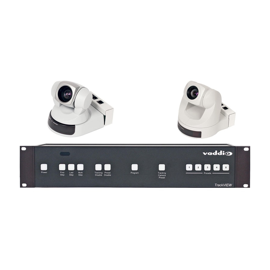
Figure 1:
TrackVIEW Controller
OVERVIEW:
The Vaddio™ TrackVIEW™ camera control system was designed to provide system integrators with an easy to
operate, fully featured and ultra flexible, multiple-mode camera tracking system. The TrackVIEW is a presenter
control system that incorporates both motion based camera tracking and camera preset tracking in one system
and has many unique features that enhance the automatic aspects of presenter actuated control systems.
KEY FEATURES:
•
Motion Tracking or Preset Tracking or Both
The system uses motion-tracking technology with Vaddio's preset camera control technology.
combination of technologies when on, allows the presenter to stay on camera as they walk between preset
camera shots which are triggered by mats or IR sensors. Motion tracking can be disabled providing for only
triggered preset tracking and preset tracking can be disabled allowing for only motion tracking.
•
First Step, Last Step and Multi-Step Modes
When using the TrackVIEW in Preset Tracking mode, the unit can be set-up to respond to the first trigger
using the AutoVIEW™ IR or StepVIEW™, the last trigger or a combination of triggers. The multi-step mode
is commonly used with multiple presenters where two triggers can be programmed into a wide shot to pick
up a larger area.
•
Two Camera System
The TrackVIEW was designed to use Sony® PTZ cameras. For the Sony systems, TrackVIEW 100, 70 and
HD1, the Sony EVI-D70 is used for the reference camera and the tracking camera is the Sony EVI-D100,
EVI-D70 and EVI-HD1 respectively. The Reference camera is adjusted to a wide-angle shot to see the
whole presentation area and the Tracking Camera looks at a smaller area and pans back and forth to follow
the movement recognized by the Reference Camera.
EZCamera™ cabling system for Cat. 5 connectivity.
•
Programming and Presets
The system has five single preset triggers that can be any combination of up to five AutoVIEW IR sensors or
StepVIEW presence sensing mats. In addition, up to ten more multi-step presets can be programmed for
wider shots when multiple presenters are working together.
Ⓒ2007 Vaddio - All Rights Reserved. Reproduction in whole or in part without written permission is prohibited. Specifications and pricing
subject to change. TrackVIEW, Quick-Connect, StepVIEW, AutoVIEW, EZCamera and PowerRite are registered trademarks of Vaddio LLC.
All other trademarks are property of their respective owners. Form Number 341-337 Rev. E
V
I
E
W
™
V
I
E
W
™
Installation and User Guide
(Patent Pending)
Both cameras are equipped with the Vaddio
This
Advertisement

Subscribe to Our Youtube Channel
Related Manuals for VADDIO TrackVIEW

Summary of Contents for VADDIO TrackVIEW
- Page 1 First Step, Last Step and Multi-Step Modes When using the TrackVIEW in Preset Tracking mode, the unit can be set-up to respond to the first trigger using the AutoVIEW™ IR or StepVIEW™, the last trigger or a combination of triggers. The multi-step mode is commonly used with multiple presenters where two triggers can be programmed into a wide shot to pick up a larger area.
-
Page 2: Intended Use
The TrackVIEW internal PowerRite power supply is sized to power the five triggers (AutoVIEW IR and StepVIEW triggers) and two PTZ cameras in the TrackVIEW 100 and 70 systems. The inputs also have a 15V/18V power selection switch for Cat. 5 power/video cables to match the cameras power requirements as the cable distance to the camera increases (see Table 1 on pg. - Page 3 TrackVIEW and Peripherals Install Guide UNPACKING: Carefully remove the products and all of the parts from the packaging. The TrackVIEW is sold in five (5) different configurations: TrackVIEW 100 TrackVIEW System with both Tracking and Reference Cameras for Smaller Rooms - Part # 999-7000-100 •...
- Page 4 (pan position for the Tracking Camera is dynamically calculated from reference camera motion detection). 10) Presets for Camera Positioning a. There are five (5) discrete camera presets that can be programmed into the TrackVIEW. 11) Rack Mount Ears Rack mount ears are included with the TrackVIEW.
- Page 5 TrackVIEW Controller Rear Panel 1) Power Input a. Note: Use only the 18VDC Power Supply Provided with the TrackVIEW. Tracking Camera Section 2) 15V/18V Power Switch a. EZCamera Cat. 5 cabling runs for Video/Power have a 15V/18V power selection switch for Cat.
- Page 6 Use only one input per Preset Trigger number. 16) RS-232 Control Input a. For use with an external control system or PC to control the TrackVIEW. 17) RS-232 Aux. Control Output For use with Pass Through Mode ON, passes control information between RS-232 ports...
-
Page 7: Installing The Cameras
(see Figure 5). The dual camera wall mount will fit all the TrackVIEW 70 and TrackVIEW 100 dual camera kits (see Figure 6). Both cameras use the EZCamera cabling shoe and are powered from the TrackVIEW controller. - Page 8 TrackVIEW 100 System The TrackVIEW 100 System uses the EVI-D70 with a wide-angle lens for the reference camera and an EVI- D100 camera for the Tracking Camera. The EVI-D100 has a 10X optical zoom lens and will work well for small room environments.
- Page 9 Connecting the TrackVIEW Cameras to the TrackVIEW Controller The TrackVIEW 70 and 100 Cameras are connected to the TrackVIEW Controller with Cat. 5 cables for video, power and control. Video and power share one Cat. 5 and control occupies the 2 Cat.
- Page 10 TrackVIEW and Peripherals Install Guide TrackVIEW HD1 System Connections The TrackVIEW HD1 tracking camera is not connected the same way as the other TrackVIEW Systems. The reference camera is connected to the TrackVIEW Controller with Cat. 5 cables for video/power and control.
- Page 11 75’ cable Cat. 5 Cat. 5 Figure 12: TrackVIEW System with two IR Sensors and two Mats connected. Note that the triggers do not use the same preset trigger number. TrackVIEW Install Guide 341-337 Rev. E Page 11 of 32...
- Page 12 Triggers used in First Step, Last Step and Multi-Step Modes When using the TrackVIEW in Preset Tracking mode, the controller can be set-up to respond to the first trigger using the AutoVIEW IR Sensor or StepVIEW Mats, the last trigger or a combination of triggers. When the preset triggers are activated, a precise camera position preset is sent to the Tracking camera with independent x/y/z coordinates than from the automatic tracking mode.
- Page 13 78” (1.98m) and the rectangle depth can range between 0” (0m) and 89” (2.26m). 78” Variable 1.98m 0 – 89” (0 – 2.26m) TrackVIEW Install Guide 341-337 Rev. E Page 13 of 32...
- Page 14 Attach sensor to mounting rails through the tile with the provided sheet metal screws. Snap on Tile Support Rails front IR sensor lens cover. Mounting Flange Sheet Metal Screws IR sensor cover TrackVIEW Install Guide 341-337 Rev. E Page 14 of 32...
- Page 15 TrackVIEW and Peripherals Install Guide Positioning the Cameras, Mats and IR Sensors (The Installation Example) In general, the cameras should be mounted close together, or with the Vaddio Dual Thin Line Wall Mount, to ensure that both cameras have the same field of view.
- Page 16 (see Figure 22). Actual control parameters are in bold type. USB Note: If the TrackVIEW is powered down while Set-up program is running, close the program, unplug and reinsert the USB connector and restart the program. Communication will be restored.
- Page 17 Reference camera’s field of view (trigger mats and IR sensors can tilt, zoom and pan the camera when stored and recalled as presets). Figure 23: Tracking Camera Set-up TrackVIEW Install Guide 341-337 Rev. E Page 17 of 32...
- Page 18 TrackVIEW and Peripherals Install Guide To Set-up the Motion Mask Setting the Motion Mask properly is essential to a successful TrackVIEW system installation. TV monitors and Screens with movement, high contrast shadows and light reflections of bright surfaces like whiteboards or glass must be masked off to ensure smooth and coherent tracking.
- Page 19 Higher values reduce the sensitivity to movement as well as noise detected as movement. Note: Yellow Highlighted Parameters - See Note on Page 21 about highlighted parameters Figure 25: Room Set-up Controls TrackVIEW Install Guide 341-337 Rev. E Page 19 of 32...
- Page 20 TrackVIEW and Peripherals Install Guide The Advanced Tab: The Advanced Control tab (see Figure 26) contains additional controls that can help tune a TrackVIEW system for an excellent performance of the auto-tracking functions. • Minimum Move setting defines the number of horizontal cells that are required to be identified as movement. These cells correspond to the motion mask cells which are 84 cells wide.
-
Page 21: Other Controls And Indicators
Tracking function is disabled. Use the front panel control (#6 on page 4) or the IR Remote control (button 5 on page 6) or click on the TrackVIEW Setup Application button status indicators (shown above) to illuminate the Tracking Disabled button bright blue before changing any of these system parameters. - Page 22 To program camera presets using the StepVIEW Mats and AutoVIEW IR Sensor, connect the mats and IR sensor to the TrackVIEW back panel as shown in Figure 28. A total of five preset triggers are available. From our installation example (Figure 20 on page 15), if three (3) mats and one (1) sensor are to be used, connect only one trigger input per preset trigger number.
-
Page 23: Putting It All Together
PUTTING IT ALL TOGETHER From our Installation Example we have referred to throughout this manual, we are using a TrackVIEW 70 System with three (3) mats and one (1) IR sensor. There are 4 established preset trigger areas and the tracking will follow the presenter across the stage until a preset trigger is activated. - Page 24 Setting Up the Triggered Preset Shots The mats and IR Sensor trigger the camera presets stored in the TrackVIEW. The following examples are recommended preset shots and the reasoning behind the shots for presentation purposes.
- Page 25 Mic & Stand Mat 1 writing. A whiteboard preset is recommended to ensure that the Seating Area camera sees all of the whiteboard. This concludes the installation example of the TrackVIEW System. TrackVIEW Install Guide 341-337 Rev. E Page 25 of 32...
- Page 26 Preset Notes: For loading Tracking camera presets 1-16, the presets 1-5 are the five single triggers (first step or last step mode) set in the memory. Presets 6 through 15 are for multi-step or combination presets. Preset 16 is the Tracking Camera Preset only. TrackVIEW Install Guide 341-337 Rev. E Page 26 of 32...
-
Page 27: General Specifications
TrackVIEW and Peripherals Install Guide GENERAL SPECIFICATIONS TrackVIEW General System Specifications Vaddio & Sony Cameras Compatible (reference camera): • Sony EVI-D70 with the Vaddio EZCamera Cabling Shoe Vaddio & Sony • Sony EVI-D100 with the Vaddio EZCamera Cabling Shoe Cameras Compatible (tracking camera): •... - Page 28 Vaddio Customer service: Vaddio will test, repair, or replace the product or products without charge if the unit is under warranty. If the product is out of warranty, Vaddio will test then repair the product or products. The cost of parts and labor charge will be estimated by a technician and confirmed by the customer prior to repair. All components must be returned for testing as a complete unit.
-
Page 29: Fcc Part 15/Ices-003 Compliance
Operation is subject to the following two conditions: (1) This device may not cause interference, and (2) This device must accept any interference including interference that may cause undesired operation of the device. Changes or modifications not expressly approved by Vaddio could void the user's authority to operate the equipment. - Page 30 Unused RS-232 Control Ports: Connections on DB-9F & DB-9M DB-9F Control In Port DB-9M Control Aux. Out Port Pins Pins Unused Unused Unused Unused Unused Unused Unused Unused Unused Unused TrackVIEW Install Guide 341-337 Rev. E Page 30 of 32...
- Page 31 TrackVIEW and Peripherals Install Guide TrackVIEW NOTES: TrackVIEW Install Guide 341-337 Rev. E Page 31 of 32...
- Page 32 Toll Free: 800-572-2011 ▪ Phone: 763-971-4400 ▪ FAX: 763-971-4464 www.vaddio.com Ⓒ2007 Vaddio - All Rights Reserved. Reproduction in whole or in part without written permission is prohibited. Specifications and pricing subject to change. TrackVIEW, Quick-Connect, StepVIEW, AutoVIEW, EZCamera and PowerRite are registered trademarks of Vaddio. All other trademarks are property of their respective owners.
Need help?
Do you have a question about the TrackVIEW and is the answer not in the manual?
Questions and answers