Advertisement
SERVICE MANUAL
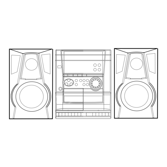
COMPACT DISC STEREO
CASSETTE RECEIVER
SYSTEM
CASSEIVER
NSX-AJ10
NSX-SZ10
NSX-SZ10E CX-NSZ10E
• This Service Manual is the "Revision Publishing" and replaces "Simple
Manual" NSX-AJ10(U)/NSX-SZ10(LH), (S/M Code No. 09-99C-424-8T1).
• If requiring information about the CD mechanism, see Service Manual
of AZG-1 ZD8RNDM, (S/M Code No. 09-001-335-3N6) and
AZG-1 ZD8RNDC, (S/M Code No. 09-001-335-3NA).
BASIC TAPE MECHANISM : ZZM-2 PR1NM / PR1NC
BASIC CD MECHANISM : AZG-1
CD
SPEAKER
CX-NAJ10
SX-NAJ12
CX-NSZ10
SX-NSZ15
SX-NSZ15
S/M Code No. 09-003-424-8R1
NSX-AJ10
NSX-SZ10
NSZ-SZ10E
CD
MECHANISM
ZD8RNDC
ZD8RNDC
ZD8RNDM
U
LH
HA
REMOTE
CONTROLLER
RC-ZAS02
Advertisement
Table of Contents

Related Manuals for Aiwa NSX-AJ10


Summary of Contents for Aiwa NSX-AJ10
- Page 1 SX-NSZ15 ZD8RNDM • This Service Manual is the “Revision Publishing” and replaces “Simple Manual” NSX-AJ10(U)/NSX-SZ10(LH), (S/M Code No. 09-99C-424-8T1). • If requiring information about the CD mechanism, see Service Manual of AZG-1 ZD8RNDM, (S/M Code No. 09-001-335-3N6) and AZG-1 ZD8RNDC, (S/M Code No. 09-001-335-3NA).
-
Page 2: Specifications
SPECIFICATIONS <HA,LH> <FM tuner section> <Compact disc player section> Tuning range 87.5 MHz to 108 MHz Laser Semiconductor laser (λ =780 nm) Usable sensitivity (IHF) 13.2 dBf D-A converter 1 bit dual Antenna terminals 75 ohms (unbalanced) Signal-to-noise ratio 85 dB (1 kHz, 0 dB) Harmonic distortion 0.05 % (1 kHz, 0 dB) <AM tuner section>... -
Page 3: Protection Of Eyes From Laser Beam During Servicing
PROTECTION OF EYES FROM LASER BEAM DURING SERVICING This set employs laser. Therefore, be sure to follow carefully the CAUTION instructions below when servicing. Use of controls or adjustments or performance of procedures other than those specified herein may result in hazardous WARNING! radiation exposure. -
Page 4: Note On Before Starting Repair
NOTE ON BEFORE STARTING REPAIR 1. Forced discharge of electrolytic capacitor of power supply block When repair is going to be attempted in the set that uses relay circuit in the power supply block, electric potential is kept charged across the electrolytic capacitors (C101, 102) even though AC power cord is removed. - Page 5 In such a case, check also if the POWER AMPLIFIER circuit or power supply circuit has any abnormalities or not. 2-2. Regarding reset There are cases that the machine does not work correctly because the MICROCOMPUTER is not reset even though the AC power cord is re-inserted, or the software reset (pressing the STOP key + POWER key) is performed.
-
Page 6: Electrical Main Parts List
ELECTRICAL MAIN PARTS LIST REF. NO. PART NO. KANRI DESCRIPTION REF. NO. PART NO. KANRI DESCRIPTION 87-010-406-080 CAP, ELECT 22-50<U> 87-010-247-080 CAP, ELECT 100-50V<LH,HA> 8A-MA6-651-010 C-IC,M38B59MFH-E250FP<U,LH> 87-010-384-080 CAP, ELECT 100-25 M 11L SME<U> 8A-NFA-615-010 C-IC,M38B57MCH-E236FP<HA> 87-010-263-080 CAP, ELECT 100-10V 87-A21-397-010 IC,STK490-070<LH,HA>... - Page 7 REF. NO. PART NO. KANRI DESCRIPTION REF. NO. PART NO. KANRI DESCRIPTION C326 87-010-198-080 CAP, CHIP 0.022 C821 87-010-405-080 CAP, ELECT 10-50V C327 87-010-196-080 CHIP CAPACITOR,0.1-25 C823 87-010-177-080 C-CAP,S 820P-50 SL C360 87-010-401-080 CAP, ELECT 1-50V C824 87-010-405-080 CAP, ELECT 10-50V C399 87-012-140-080 CAP 470P...
- Page 8 REF. NO. PART NO. KANRI DESCRIPTION REF. NO. PART NO. KANRI DESCRIPTION C108 87-010-178-080 CHIP CAP 1000P WH181 87-A90-460-010 HLDR,WIRE 2.5-7P<U> C109 87-012-369-080 C-CAP,S 0.047-50F C110 87-010-197-080 CAP, CHIP 0.01 DM C111 87-010-196-080 CHIP CAPACITOR,0.1-25 C113 87-010-178-080 CHIP CAP 1000P C114 87-010-154-080 CAP CHIP 10P...
-
Page 9: Transistor Illustration
TRANSISTOR ILLUSTRATION S D G E C B E C B B C E 2SB1370 2SJ460 CSA952 DTC114ES 2SB1342 2SK2541 CSC4115 2SD1933 KTA1266 KTC3198 KTC3199 E B C B C E KRA102 2SC3331 CC5551 2SA1235 KRA107 2SC2714 2SC3052 KRC102 CMBT5401 KRC104 CMBT5551 CHIP RESISTOR PART CODE... - Page 10 WIRING - 1 (MAIN) <U> - 10 -...
- Page 11 SCHEMATIC DIAGRAM - 1 (MAIN : 1 / 2) <U> – 11 –...
- Page 12 SCHEMATIC DIAGRAM - 2 (MAIN : 2 / 2) <U> – 12 –...