Table of Contents
Advertisement
Advertisement
Table of Contents

Subscribe to Our Youtube Channel
Related Manuals for Gigabyte GA-K8RS482M-FS-02


Summary of Contents for Gigabyte GA-K8RS482M-FS-02
- Page 1 GA-K8RS482M-FS-02 AMD Socket 939 Processor Motherboard User's Manual Rev. 1001...
-
Page 2: Atx_12V
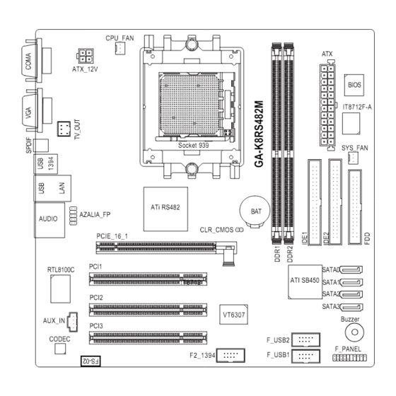
GA-K8RS482M-FS-02 Motherboard Layout CPU_FAN ATX_12V BIOS IT8712F-A Socket 939 SYS_FAN ATi RS482 AZALIA_FP AUDIO CLR_CMOS PCIE_16_1 PCI1 RTL8100C SATA0 ATI SB450 IT8712 SATA1 SATA2 PCI2 SATA3 VT6307 Buzzer AUX_IN PCI3 CODEC F_USB2 F_PANEL F_USB1 F2_1394 - 2 -... -
Page 3: Block Diagram
Block Diagram CPUCLK+/-(200MHz) AMD K8 Socket 939 DDR 400/333/266/200MHz DIMM Dual Channel Memory Host Interface SBLINK_CLK P/N (100MHz) NBSRC_CLK P/N (100MHz) NB_OSC (14.318MHz) RS482 PCIE_16_1 66MHz SBSRC_CLK P/N (100MHz) 33MHz 14.318MHz 48MHz PCI-ECLK BIOS (100MHz) PCI Express x16 4 Serial ATA ATA33/66/100/ PCI Bus SB450... -
Page 4: Feature Summary
Chapter 1 Hardware Installation Feature Summary Socket 939 for AMD Althlon 64 / 64FX / Sempron processor (K8) HT 1.03 (FSB 800/1000MHz) Supports core frequencies in excess of 3000+ and faster Chipset North Bridge: ATi RS482 South Bridge: ATI SB450 supported on the Win 2000/XP operating systems Memory 2 DDR DIMM memory slots... - Page 5 Hardware Monitor System voltage detection CPU temperature detection CPU / System fan speed detection CPU warning temperature CPU / System fan failure warning CPU smart fan control Onboard SATA RAID Onboard SB450 chipset supports data striping (RAID 0) or mirroring (RAID 1) function supports data transfer rate of up to 150 MB/s supports hot plugging function supports a maximum of 4 SATA connections...
- Page 6 I/O Back Panel Introduction COM A (Serial Port) Connects to serial-based mouse or data processing devices. VGA Port Monitor can be connected to VGA port. OPTICAL (SPDIF Out) The SPDIF optical output port is capable of providing digital audio to external speakers or com pressed AC3 data to an external Dolby Digital Decoder via an optical cable.
-
Page 7: Table Of Contents
Connectors Introduction 12 14 1) ATX_12V 8) F_PANEL 2) ATX (Power Connector) 9) AZALIA_FP 3) CPU_FAN 10) AUX_IN 4) SYS_FAN 11) F_USB1 / F_USB2 5) FDD 12) F2_1394 6) IDE1 / IDE2 13) CLR_CMOS 7) S_ATA0 / S_ATA1 / S_ATA2 / S_ATA3 14) BAT 15) TV_OUT - 7 -... - Page 8 1/2) ATX_12V/ATX (Power Connector) With the use of the power connector, the power supply can supply enough stable power to all the components on the motherboard. Before connecting the power connector, please make sure that all components and devices are properly installed. Align the power connector with its proper location on the motherboard and connect tightly.
- Page 9 3/4) CPU_FAN / SYS_FAN (Cooler Fan Power Connector ) The cooler fan power connector supplies a +12V power voltage via a 3-pin power connector and possesses a foolproof connection design. Most coolers are designed with color-coded power connector wires. A red power connector wire indicates a positive connection and requires a +12V power voltage.
-
Page 10: S_Ata0/S_Ata1/S_Ata2/S_Ata3
6) IDE1 / IDE2 (IDE Connector) An IDE device connects to the computer via an IDE connector. One IDE connector can connect to one IDE cable, and the single IDE cable can then connect to two IDE devices (hard drive or optical drive). -
Page 11: F_Panel
8) F_PANEL (Front Panel Jumper) Please connect the power LED, PC speaker, reset switch and power switch etc. of your chassis front panel to the F_PANEL connector according to the pin assignment below. Message LED/ Power Power/ Switch Sleep LED IDE Hard Disk Reset Switch Active LED... -
Page 12: Aux_In
10) AUX_IN (AUX In Connector, White) Connect other device (such as PCI TV Tuner audio out) to the connector. Pin No. Definition AUX-L AUX -R 11) F_ USB1 / F_USB2 (Front USB Connector) Be careful with the polarity of the front USB connector. Check the pin assignment carefully while you connect the front USB cable, incorrect connection between the cable and connector will make the device unable to work or even damage it. -
Page 13: F2_1394
12) F2_1394 (IEEE 1394 Connector) Serial interface standard set by Institute of Electrical and Electronics Engineers, which has features like high speed, high bandwidth and hot plug. Be careful with the polarity of the IEEE1394 connector. Check the pin assignment carefully while you connect the IEEE1394 cable, incorrect connection between the cable and connector will make the device unable to work or even damage it. -
Page 14: Tv_Out
14) BAT(Battery) If you want to erase CMOS... 1.Turn OFF the computer and unplug the power cord. 2. Take out the battery gently and put it aside for about 10 minutes (Or you can use a metal object to connect the positive and negative pins in the battery holder to make them short for one minute). - Page 15 Chapter 2 BIOS Setup BIOS (Basic Input and Output System) includes a CMOS SETUP utility which allows user to configure required settings or to activate certain system features. The CMOS SETUP saves the configuration in the CMOS SRAM of the motherboard. When the power is turned off, the battery on the motherboard supplies the necessary power to the CMOS SRAM.
- Page 16 Optimized Defaults indicates the value of the system parameters which the system would be in best performance configuration. Set Supervisor Password Change, set, or disable password. It allows you to limit access to the system and Setup, or just to Setup. GA-K8RS482M-FS-02 Motherboard - 16 -...
- Page 17 Set User Password Change, set, or disable password. It allows you to limit access to the system. Save & Exit Setup Save CMOS value settings to CMOS and exit setup. Exit Without Saving Abandon all CMOS value changes and exit setup. - 17 - BIOS Setup...
-
Page 18: Standard Cmos Features
Cylinder Number of cylinders Head Number of heads Precomp Write precomp Landing Zone Landing zone Sector Number of sectors If a hard disk has not been installed, select NONE and press <Enter>. GA-K8RS482M-FS-02 Motherboard - 18 -... - Page 19 Drive A The category identifies the types of floppy disk drive A that has been installed in the computer. None No floppy drive installed 360K, 5.25" 5.25 inch PC-type standard drive; 360K byte capacity. 1.2M, 5.25" 5.25 inch AT-type high-density drive; 1.2M byte capacity (3.5 inch when 3 Mode is Enabled).
-
Page 20: Advanced Bios Features
Select boot sequence for onboard(or add-on cards) SCSI, RAID, etc. Use < > or < > to select a device, then press<+> to move it up, or <-> to move it down the list. Press <ESC> to exit this menu. GA-K8RS482M-FS-02 Motherboard - 20 -... - Page 21 First / Second / Third Boot Device Floppy Select your boot device priority by Floppy. LS120 Select your boot device priority by LS120. Hard Disk Select your boot device priority by Hard Disk. CDROM Select your boot device priority by CDROM. Select your boot device priority by ZIP.
-
Page 22: Integrated Peripherals
Support SATA RAID function IDE Controller Set onboard SATA type to IDE Controller.(Default value) RAID Controller Set onboard SATA type to RAID Controller. Onboard LAN function Enabled Enable Onboard H/W LAN function. (Default value) Disabled Disable this function. GA-K8RS482M-FS-02 Motherboard - 22 -... - Page 23 Onboard H/W 1394 Enabled Enable onboard IEEE 1394 function.(Default value) Disabled Disable this function. On-Chip USB 1.1 Controller Disable USB1.1 Host Controller if you are not using high speed USB devices. Enabled Enable USB 1.1 Controller. (Default value) Disabled Disable USB 1.1 Controller. On-Chip USB 2.0 Controller Disable USB2.0 Host Controller if you are not using high speed USB devices.
-
Page 24: Power Management Setup
Enabled Enable alarm function to POWER ON system. If RTC Alarm Lead To Power On is Enabled. Date (of Month) Alarm : Everyday, 1~31 Time (hh: mm: ss) Alarm : (0~23) : (0~59) : (0~59) GA-K8RS482M-FS-02 Motherboard - 24 -... - Page 25 PnP/PCI Configurations CMOS Setup Utility-Copyright (C) 1984-2005 Award Software PnP/PCI Configurations PCI 1 IRQ Assignment [Auto] Item Help PCI 2 IRQ Assignment [Auto] Menu Level PCI 3 IRQ Assignment [Auto] : Move Enter: Select +/-/PU/PD: Value F10: Save ESC: Exit F1: General Help F5: Previous Values F7: Default Setting...
-
Page 26: Pc Health Status
CPU fan speed will change depending on the actual CPU temperature. c . When the CPU temperature is lower than 40 degrees Celsius, CPU fan will keep turning at lower speed. Disabled Disable the CPU Smart FAN Control function. GA-K8RS482M-FS-02 Motherboard - 26 -... -
Page 27: Load Optimized Defaults
Load Fail-Safe Defaults CMOS Setup Utility-Copyright (C) 1984-2005 Award Software Standard CMOS Features Load Fail-Safe Defaults Advanced BIOS Features Load Optimized Defaults Integrated Peripherals Set Supervisor Password Power Management Setup Set User Password Load Fail-Safe Defaults (Y/N)? N PnP/PCI Configurations Save &... - Page 28 Setup Menu. If you select "Setup" at "Password Check" in Advance BIOS Features Menu, you will be prompted only when you try to enter Setup. GA-K8RS482M-FS-02 Motherboard - 28 -...
-
Page 29: Exit Without Saving
2-10 Save & Exit Setup CMOS Setup Utility-Copyright (C) 1984-2005 Award Software Standard CMOS Features Load Fail-Safe Defaults Advanced BIOS Features Load Optimized Defaults Integrated Peripherals Set Supervisor Password Power Management Setup Set User Password PnP/PCI Configurations Save & Exit Setup Save to CMOS and EXIT (Y/N)? Y PC Health Status Exit Without Saving...
Need help?
Do you have a question about the GA-K8RS482M-FS-02 and is the answer not in the manual?
Questions and answers