Advertisement

TopPage
In the interests of user-safety (Required by safety regulations in some countries) the set should be restored to its orig-
inal condition and only parts identical to those specified should be used.
SAFETY PRECAUTION
CAUTION............................................... . ............ i
End of life disposal................................. . .......... iii
MAJOR SERVICE PARTS..................... . .......... iv
[1]
SPECIFICATIONS (LC-52,60LE830E/
RU,831E/S)............................................ . ........1-1
[2]
CHAPTER 2. OPERATION MANUAL
[1]
Parts Name ............................................ . ........2-1
[2]
OPERATION MANUAL .......................... . ........2-5
CHAPTER 3. DIMENSIONS
[1]
S/833E).................................................. . ........3-1
[2]
S/833E).................................................. . ........3-2
[1]
REMOVING OF MAJOR PARTS (LC-
52LE830E,RU/831E,S/833E) ................ . ........4-1
[2]
60LE830E,RU/831E,S/833E) ................ . ........4-6
[3]
sheet ...................................................... . ......4-11
Parts marked with "
" are important for maintaining the safety of the set. Be sure to replace these parts with specified ones for maintaining the
safety and performance of the set.

SERVICE MANUAL

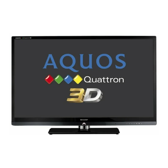
LCD COLOUR TELEVISION
LC-52/60LE830E/RU
LC-52/60LE831E/S
LC-52/60LE833E
MODELS
CONTENTS
LC-52/60LE830E,RU/831E,S/833E
No. S81T252LE830E
[4]
Precautions for assembly ............................ 4-13
[5]
CHAPTER 5. ADJUSTMENT
[1]
ADJUSTMENT PROCEDURE ...................... 5-1
CHAPTER 6. TROUBLESHOOTING TABLE
[1]
TROUBLESHOOTING TABLE ...................... 6-1
[2]
error............................................................. 6-18
[1]
MAJOR IC INFORMATIONS......................... 7-1
[1]
52LE830E, RU/833E).................................... 8-1
[2]
52LE831E, S) ................................................ 8-2
[3]
60LE830E, RU/833E).................................... 8-3
[4]
60LE831E, S) ................................................ 8-4
[5]
SYSTEM BLOCK DIAGRAM (LC-52/
60LE830E, RU/833E).................................... 8-5
[6]
SYSTEM BLOCK DIAGRAM (LC-52/
60LE831E, S) ................................................ 8-6
This document has been published to be used for
after sales service only.
The contents are subject to change without notice.

Advertisement

Table of Contents
loading

Summary of Contents for Sharp LC-52/60LE833ELC-60LE830E

  • Page 1: Table Of Contents

    TopPage LC-52/60LE830E,RU/831E,S/833E SERVICE MANUAL No. S81T252LE830E LCD COLOUR TELEVISION LC-52/60LE830E/RU LC-52/60LE831E/S LC-52/60LE833E MODELS In the interests of user-safety (Required by safety regulations in some countries) the set should be restored to its orig- inal condition and only parts identical to those specified should be used. CONTENTS SAFETY PRECAUTION Precautions for assembly ......
  • Page 2: Important Service Safety Pre

    LC-52/60LE830E,RU/831E,S/833E LC52LE830E SAFETY PRECAUTION Service Manual IMPORTANT SERVICE SAFETY PRECAUTION Service work should be performed only by qualified service technicians who are thoroughly familiar with all safety checks and the servicing guidelines which follow: WARNING • Use an AC voltmeter having with 5000 ohm per volt, or higher, sen- sitivity or measure the AC voltage drop across the resistor.
  • Page 3: Precautions For Using Lead-Free Solder

    LC-52/60LE830E,RU/831E,S/833E Precautions for using lead-free solder Employing lead-free solder • “PWBs” of this model employs lead-free solder. The LF symbol indicates lead-free solder, and is attached on the PWBs and service manuals. The alphabetical character following LF shows the type of lead-free solder. Example: F a/a Indicates lead-free solder of tin, silver and copper.
  • Page 4: End Of Life Disposal

    LC-52/60LE830E,RU/831E,S/833E End of life disposal End of life disposal...
  • Page 5: Outline

    LC-52/60LE830E,RU/831E,S/833E LC52LE830E OUTLINE Service Manual MAJOR SERVICE PARTS PWB Unit Ref No. Parts No. Description DKEYDF733FM51 MAIN Unit (LC-52/60LE830E,RU) DKEYDF733FM52 MAIN Unit (LC-52/60LE831E,S) DKEYDF733FM54 MAIN Unit (LC-52/60LE833E) DUNTKF494FM02 R/C OPERATION Unit DUNTKF770FM51 ICON Unit RUNTKA869WJQZ TOUCH SENSOR Unit RUNTKA819WJQZ 3D IR TRANSMITTER Unit RUNTKA795WJQZ POWER SUPPLY Unit (LC-52LE830E,RU/831E,S/833E) RUNTKA799WJN1...
  • Page 6: Chapter 1. Specifications

    Standby power consumption applies when the TV is set to not receive EPG data. As a part of our policy of continuous improvement, SHARP reserves the right to make design and specification changes for product improvement without prior notice. The performance specification figures indicated are nominal values of production units.
  • Page 7: Specifications (Lc-52,60Le833E)

    Standby power consumption applies when the TV is set to not receive EPG data. As a part of our policy of continuous improvement, SHARP reserves the right to make design and specification changes for product improvement without prior notice. The performance specification figures indicated are nominal values of production units.
  • Page 8: Parts Name

    LC-52/60LE830E,RU/831E,S/833E CHAPTER 2. LC52LE830E OPERATION MANUAL Service Manual [1] Parts Name TV (front view) Illumination LED* 3D infrared emitter* OPC sensor Remote control sensor 3D mode: Blue illumination 2D mode: White illumination This panel emits infrared signal towards the 3D glasses you wear when viewing 3D images.
  • Page 9: Important Information

    LC-52/60LE830E,RU/831E,S/833E TV (rear view) — continued MAIN POWER switch* SD CARD (VIDEO STORE) slot OUTPUT (Headphones/ AUDIO (L/R)) terminal* USB 1 port HDMI 1 (HDMI/ARC) terminal HDMI 2 (HDMI) terminal HDMI 3 (HDMI) terminal RS-232C terminal HDMI 4 (HDMI) terminal PC terminal EXT 1 (RGB) terminal EXT 2 (VIDEO/AUDIO...
  • Page 10 LC-52/60LE830E,RU/831E,S/833E Remote contr ol unit 1 TV (Standby/On) 2 ATV Access conventional analogue TV mode. Access digital TV mode. Access satellite mode. RADIO DTV/SAT: Switch between radio and data mode. When only data broadcasting (no radio broadcasting) is transmitted by DVB, the radio broadcasting will be skipped.
  • Page 11 LC-52/60LE830E,RU/831E,S/833E (Mute) TV sound on/off. ATV/DTV/SAT: Select the TV channel. NET: Scrolls pages up/down. (Volume) Increase/decrease TV volume. 21 EPG DTV/SAT: Display the EPG screen. 11 MENU “Menu” screen on/off. (Return) ATV/DTV/SAT: Return to the previous 12 3D “Menu” screen. Select between 3D and 2D image NET: Return to the previous page (This viewing.
  • Page 12: Attaching The Stand Unit

    LC-52/60LE830E,RU/831E,S/833E [2] OPERATION MANUAL Preparation Attaching the stand unit Before performing work, spread cushioning over the Insert and tighten middle screws into the holes surface on which you will be laying the TV. This will on the rear of the TV. prevent it from being damaged.
  • Page 13: Dimensions (Lc-52Le830E, Ru/831E, S/833E)

    LC-52/60LE830E,RU/831E,S/833E CHAPTER 3. LC52LE830E DIMENSIONS Service Manual [1] DIMENSIONS (LC-52LE830E, RU/831E, S/833E) Unit: mm (26.4) (26,4) (33.4) (33,4) (142.0) (1206.0) (1206,0) (142,0) (1152.0) (1152,0) (507.0) (298.0) (507,0) (298,0) (400.0) (400,0) (215.0) (215,0) *1 Active area *2 Thinnest part *3 Excluding projecting part NOTE Dimensions do not include protrusions such as screws and some parts.
  • Page 14: Dimensions (Lc-60Le830E, Ru/831E, S/833E)

    LC-52/60LE830E,RU/831E,S/833E [2] DIMENSIONS (LC-60LE830E, RU/831E, S/833E) Unit: mm (26.4) (26,4) (33.4) (33,4) (1383.0) (169.0) (169,0) (1383,0) (1329.12) (1329,12) (355.0) (536.0) (355,0) (536,0) (400.0) (400,0) (215.0) (215,0) *1 Active area *2 Thinnest part *3 Excluding projecting part NOTE Dimensions do not include protrusions such as screws and some parts. 3 –...
  • Page 15: Chapter 4. Removing Of Major Parts

    LC-52/60LE830E,RU/831E,S/833E CHAPTER 4. LC52LE830E REMOVING OF MAJOR PARTS Service Manual [1] REMOVING OF MAJOR PARTS (LC-52LE830E,RU/831E,S/833E) 1. Removing of Stand Unit and Rear Cabinet Ass’y. 1. Remove the 1 lock screw and detach the Stand Support Cover 2. Remove the 4 lock screws and detach the Stand Unit 3.
  • Page 16: Bottom Cover

    LC-52/60LE830E,RU/831E,S/833E 2. Removing of Speaker-L/R. 1. Remove the 8 lock screws and detach the Stand T-CON Angle 2. Detach the Bottom Cover 3. Disconnect SP wire. 4. Detach the Speaker-L , Speaker-R MAIN Unit [SP] 3 Bottom Cover 2 Stand T-CON Angle [SP] Speaker-R Speaker-L...
  • Page 17: Main Unit

    LC-52/60LE830E,RU/831E,S/833E 3. Removing of Speaker-L/R. 1. Disconnect the following connectors from the MAIN Unit. (SB, PD, LW, PL, RC, CI) 2. Disconnect the following connectors from the POWER SUPPLY Unit. (PD, L1, AS) 3. Disconnect the following connectors from the LCD Control Unit. (LW, PL) POWER SUPPLY Unit MAIN Unit [PD]...
  • Page 18 LC-52/60LE830E,RU/831E,S/833E 4. Removing of MAIN Unit, POWER/LED Drive Unit, Speaker (Sub Woofer), 52” LCD Panel Module Unit. 1. Remove the 5 lock screws and detach the Main PWB Shield 2. Remove the 2 lock screws and detach the MAIN Unit 3.
  • Page 19: Operation Unit

    LC-52/60LE830E,RU/831E,S/833E 5. Removing of R/C, Operation Unit, ICON Unit, 3D IR Emitter Unit, Touch Sensor Unit. 1. Remove the 1 lock screw and detach the ICON Unit 2. Detach the R/C, Operation Unit 3. Detach the 3D IR Emitter Unit 4.
  • Page 20: Removing Of Major Parts (Lc 60Le830E,Ru/831E,S/833E)

    LC-52/60LE830E,RU/831E,S/833E [2] REMOVING OF MAJOR PARTS (LC-60LE830E,RU/831E,S/833E) 1. Removing of Stand Unit and Rear Cabinet Ass’y. 1. Remove the 2 lock screws and detach the Stand Support Cover 2. Remove the 4 lock screws and detach the Stand Unit 3. Remove the 1 lock screw and detach the AC Cord Cover 4.
  • Page 21 LC-52/60LE830E,RU/831E,S/833E 2. Removing of Speaker-L/R. 1. Remove the 2 lock screws and the 1 lock screw detach the Bottom Cover 2. Remove the 14 lock screws and detach the Fixing Metal Angle 3. Disconnect SP wire. 4. Detach the Speaker-L , Speaker-R MAIN Unit [SP]...
  • Page 22 LC-52/60LE830E,RU/831E,S/833E 3. Removing of Connectors. 1. Disconnect the following connectors from the MAIN Unit. (SB, PD, LW, PL, RC, CI) 2. Disconnect the following connectors from the POWER SUPPLY Unit. (PD, L1, AS) 3. Disconnect the following connectors from the LCD Control Unit. (LW, PL) POWER SUPPLY Unit MAIN Unit [PD]...
  • Page 23 LC-52/60LE830E,RU/831E,S/833E 4. Removing of MAIN Unit, POWER/LED Drive Unit, speaker (Sub Woofer), 60” LCD Panel Module Unit. 1. Remove the 5 lock screws and detach the Main PWB Shield 2. Remove the 2 lock screws and detach the MAIN Unit 3.
  • Page 24 LC-52/60LE830E,RU/831E,S/833E 5. Removing of R/C, Operation Unit, ICON Unit, 3D IR Emitter Unit, Touch Sensor Unit. 1. Remove the 1 lock screw and detach the ICON Unit 2. Detach the R/C, Operation Unit 3. Detach the 3D IR Emitter Unit 4.
  • Page 25: The Location Putting On The Heat Measure Sheet

    LC-52/60LE830E,RU/831E,S/833E [3] The location putting on the heat measure sheet 1. MAIN PWB Unit Main PWB Unit (DUNTKF733WE**) PSPAZC702WJKZ The object to cool. (The sheet is put on the back of the board.) The guide line is impressed on the backlight chassis 4 –...
  • Page 26 LC-52/60LE830E,RU/831E,S/833E 2. LCD Control Unit The IC to cool LCD control unit (RUNTK4909TP**) Please put [PSPAZC062WJKZ] on the IC 4 – 12...
  • Page 27: Precautions For Assembly

    LC-52/60LE830E,RU/831E,S/833E [4] Precautions for assembly 1. Attaching the touch sensor 1. After removing the release paper, attach the touch sensor keeping out dust and dirt. 2. Press the 3 circular silk positions on the PWB to fix the touch sensor. There is no problem if the pressing positions are slightly misaligned. How- ever, do not press the connectors directly since they are very easy to break.
  • Page 28 LC-52/60LE830E,RU/831E,S/833E State where the main PWB and shielded case are assembled Access hole Access hole The following is a drawing mounting the main PWB Ass’y on the backlight chassis. (The parts indicated by -> are the access holes for confirmation.) (Main PWB Ass’y =>...
  • Page 29: The Way Of Detaching Rear Cabinet

    LC-52/60LE830E,RU/831E,S/833E [5] The way of detaching Rear Cabinet • Here are the way of detaching Rear Cabinet. Please respond in following order. 1. Lay the TV set down on the desk or table with the glass side down, set the left hand between Front Cabinet and Rear Cabinet on the bottom of right corner side.
  • Page 30 LC-52/60LE830E,RU/831E,S/833E 3. Push Rear Cabinet toward the center of TV set with right hand. At the same time, open Rear Cabinet in the back side with left hand and detach the hook. Figure for image Right Hand Left Hand 4. Detach the hooks one by one in a counterclockwise direction with changing the position of right hand. Follow the arrows for removing Start Position 4 –...
  • Page 31: Adjustment Procedure

    LC-52/60LE830E,RU/831E,S/833E CHAPTER 5. LC52LE830E ADJUSTMENT Service Manual [1] ADJUSTMENT PROCEDURE 1. Adjustment method after PWB and/or IC replacement due to repair The unit is set to the optimum at the time of shipment from the factory. If any value should become improper or any adjustment is necessary due to the part replacement, make an adjustment according to the following pro- cedure.
  • Page 32 LC-52/60LE830E,RU/831E,S/833E 2. Notes of Touch sensor key unit Touch sensor key unit (RUNTKA869WJQZ) is fixed directly in Front Cabinet. The unit cannot never be recycled when exfoliated from Front Cabinet. Therefore, please exchange the touch sensor units when Front Cabinet is changed. 3.
  • Page 33 LC-52/60LE830E,RU/831E,S/833E 6. Description of display (1) Present page / number of total pages (4) Inducing display (3) Present colour system (2) Input that has been selected now (5) Inch setting and Model name display 1/24 INPUT1 AUTO EURO MAIN Version 1.00 (E 2010/**/** ) BOOT Version xxxxxxx...
  • Page 34 LC-52/60LE830E,RU/831E,S/833E 7. List of adjustment process mode menu The character string in brackets [ ] will appear as a page title in the adjustment process menu header. Page Line Item Description Remarks (adjustment detail, etc.) 1/24 [INFO] MAIN Version 1xxx(xxxxx) Main software version BOOT Version xxxxxxx...
  • Page 35 LC-52/60LE830E,RU/831E,S/833E Page Line Item Description Remarks (adjustment detail, etc.) 6/24 [COMP15KMAIN] COMP15K ALL ADJ Enter Component 15K picture level adjustment COMP15K MAIN Y GAIN Y GAIN adjustment value COMP15K MAIN CB GAIN Cb GAIN adjustment value COMP15K MAIN CR GAIN Cr GAIN adjustment value COMP15K Y OFFSET Y OFFSET adjustment value...
  • Page 36 LC-52/60LE830E,RU/831E,S/833E Page Line Item Description Remarks (adjustment detail, etc.) 15/24 3DHDMI FPGA Version xxxxx 2D→3D FPGA Version xxxxx 3D IR EMITTER CONTROL xxxxx 16/24 [FR REGI] POWER LED BRIGHTNESS MENU LED BRIGHTNESS INPUT LED BRIGHTNESS CH UP LED BRIGHTNESS CH DOWN LED BRIGHTNESS VOL UP LED BRIGHTNESS VOL DOWN LED BRIGHTNESS LOGO LED BRIGHTNESS...
  • Page 37 LC-52/60LE830E,RU/831E,S/833E Page Line Item Description Remarks (adjustment detail, etc.) 23/24 [ETC] ERROR STANDBY CAUSE1 NO RECORD ERROR STANDBY CAUSE ERROR STANDBY CAUSE2 NO RECORD ERROR STANDBY CAUSE3 NO RECORD ERROR STANDBY CAUSE4 NO RECORD ERROR STANDBY CAUSE5 NO RECORD STANDBY CAUSE RESET Reset stand by cause.
  • Page 38: Special Features

    LC-52/60LE830E,RU/831E,S/833E 8. Special features 1. NORMAL STANDBY CAUSE (Page 1/24) Display of a cause (code) of the last standby. The cause of the last standby is recorded in EEPROM whenever it is possible. Checking this code will be useful in finding a problem when you repair the troubled set. 2.
  • Page 39 LC-52/60LE830E,RU/831E,S/833E 9. Lamp Error detection 1. Function This LCD color TV set incorporates a Lamp error detection feature that automatically turns off the power for safety under abnormal lamp or lamp circuit conditions. If by any chance anything is wrong with the lamp or lamp circuit or if the lamp error detection feature is activated for some rea- son, the following will result.
  • Page 40 LC-52/60LE830E,RU/831E,S/833E 10. Public Mode 1. Starting the Public Mode • There are two following ways to display the PUBLIC Mode setting screen. 1) Method of needing password a) Turn off the power, refer to “3. Method of shuts down for Power supply”. b) While holding down the “INPUT”...
  • Page 41 LC-52/60LE830E,RU/831E,S/833E 5. Operation after “RESET” Select “RESET” in the PUBLIC Mode, and it operates as follows when it is executed (refer to the basic operation). • The set contents in the PUBLIC mode are initialized. • It does not exit the PUBLIC mode. •...
  • Page 42 LC-52/60LE830E,RU/831E,S/833E 4) Volume fixed [VOLUME FIXED] Option “VARIABLE”, “FIXED”, “ACCTRL” or “AC/RCCTRL” (loop enabled) Default “VARIABLE” Function • VARIABLE : The volume is not fixed. • FIXED : The volume is fixed to the value adjusted in the volume fixed level. •...
  • Page 43 LC-52/60LE830E,RU/831E,S/833E 8) Menu operation [MENU BUTTON] Option “RESPOND” or “NO RESPOND” (loop enabled) Default “RESPOND” Function The MENU key on the main unit and remote control is decided whether it is enabled or disabled. Exception • RESPOND : The manu key is enabled. •...
  • Page 44 LC-52/60LE830E,RU/831E,S/833E 11) Start mode [INPUT MODE START] Option “NORMAL” or “Input source 1 (input selection or channel)” ... (loop enabled) Default “NORMAL” Function Which kinds of input source or channel is decided when the power turning on. NORMAL : The content of the last memory is followed. Remarks •...
  • Page 45 LC-52/60LE830E,RU/831E,S/833E 15) 232C power ON control [232C POWON] Option “ENABLE” or “DISABLE” (loop enabled) Default DISABLE Function The item decide whether Power ON by the 232C command is enabled/disabled in the standby state. The same function as 232C command “RSPW”. ENABLE : POWR0001 is always enabled.
  • Page 46 LC-52/60LE830E,RU/831E,S/833E 4. Restriction of Copy Mode • USB thumb drive should be more than 1Mbyte. • File system of USB thumb drive should be FAT (FAT32). • More than one USB thumb drive shouldn't be connected to TV. • All USB terminals can be valid, but more than one USB thumb drive shouldn't be connected to TV. •...
  • Page 47 LC-52/60LE830E,RU/831E,S/833E 6. Operating 1) Copy mode (TV USB) Copy mode Execute start in Copy Mode setting screen. [Start If USB device is detected by TV, focus is not appropriated to items. [Start Execcute Copy mode [Wait ] is displayed while executing it. [Wait...
  • Page 48: Video Signal Adjustment Procedure

    LC-52/60LE830E,RU/831E,S/833E 12. Video signal adjustment procedure The adjustment process mode menu is listed in Section 5. Signal generator level adjustment check. (Adjustment to the specified level) : 0.7Vp-p ± 0.02Vp-p (Pedestal to white level) • Composite signal PAL : 0.7Vp-p ± 0.02Vp-p (Pedestal to white level) •...
  • Page 49 LC-52/60LE830E,RU/831E,S/833E 12.5. ADC adjustment (Component 15K) Adjustment point Adjustment conditions Adjustment procedure Setting [Signal] • Feed the COMPONENT 15K 100% full field colour bar signal (100% colour COMP15K, 50Hz saturation) to EXT3 COMPONENT IN. 100% Full field colour bar Signal [Terminal] 100% white Black...
  • Page 50: White Balance Adjustment

    LC-52/60LE830E,RU/831E,S/833E 13. White balance adjustment For white balance adjustment, adjust the offset values on pages 11/24. [Condition of the unit for inspection] : Modulated light (+16) AV MODE: DYNAMIC Active Backlight: OFF OPC: OFF Asing Time: Min, 60 minute [Input signal condition] : HDMI 1080i 15IRE (LO), 78IRE (HI) [Adjustment reference device] : Minolta CA-210...
  • Page 51: Initialization To Factory Settings

    LC-52/60LE830E,RU/831E,S/833E 15. Initialization to factory settings CAUTION: When the factory settings have been made, all user setting data, including the channel settings, are initialized. (The adjustments done in the adjustment process mode are not initialized.) Keep this in mind when initializing these settings. Adjustment item Adjustment conditions Adjustment procedure...
  • Page 52 LC-52/60LE830E,RU/831E,S/833E 5. After a while, if software update file is detected in the USB memory device, the following screen shows up. Select OK when if there is no problem. NOTE: If USB memory device isn’t correctly inserted in TV, caution shows up. Please insert USB memory device and retry software update.
  • Page 53 LC-52/60LE830E,RU/831E,S/833E 8. When all the procedures are complete, the following upgrade success screen shows up. The new software version can be confirmed on screen. After a while, Turn off power and boot-up automaticaly. NOTE: TV is restarted automaticaly, the AC code need not be pulled out. [Information Software update USB update]...
  • Page 54: Troubleshooting Table

    LC-52/60LE830E,RU/831E,S/833E CHAPTER 6. LC52LE830E TROUBLESHOOTING TABLE Service Manual [1] TROUBLESHOOTING TABLE No power (Central Icon LED failure to light up) or No startup (Central Icon LED is flashing) Is the AC cord connector tightly connected to the set? Reconnect the AC cord tightly and turn on the power again. Are the wire harnesses and other cables properly connected to Reconnect the wire harnesses and other cables properly to the the set?
  • Page 55 LC-52/60LE830E,RU/831E,S/833E The sound is not emitted from the Speaker & Woofer though the picture has come out. No sound output in all modes? Do audio signals output from pins [Y30/CPU_AOLRCK, Y31/ Check IC3303 and its peripheral circuits. CPU_AOBCK, V27/CPU_AOSDATA0] of IC3303 (Digital AV decode &...
  • Page 56 LC-52/60LE830E,RU/831E,S/833E No sound (during the reception of TV (ANALOG) broadcasting) Does not the sound go out though the picture has come out when UHF/VHF is received? In the case of LE830,LE833 series, refer to (A). In the case of LE831 series, refer to (B). Does SIF signal output from pin (8) of TUNER Check the tuner and its peripheral circuits.
  • Page 57 LC-52/60LE830E,RU/831E,S/833E No sound (during the reception of TV (DIGITAL) broadcasting) Does not the sound go out though the picture has come out when DTV is received? In the case of LE830,LE833 series, refer to (A). In the case of LE831 series, refer to (B). Do IF signals output to pins [10, 11] of TUNER Check the tuner and its peripheral circuits.
  • Page 58 LC-52/60LE830E,RU/831E,S/833E No sound (during the reception of TV (DIGITAL-Satellite) broadcasting) (DIGITAL-Satellite is only function for LE830,LE833 series) Does not the sound go out though the picture has come out when DTV is received? Do TS signals output to pins [44/TS_TUOUT_CLK, 46/ Check the tuner and its peripheral circuits.
  • Page 59 LC-52/60LE830E,RU/831E,S/833E No sound from external input devices (2) Does not the sound of the audio signal input to EXT2 go out? • Do audio signals input to pins[2/CVBS1_IN_R, 3/ Check the setting of an external input device that connects with CVBS1_IN_L] of EXT2 (J511)? EXT2.
  • Page 60 LC-52/60LE830E,RU/831E,S/833E No sound from external input devices (5) Does not the sound of the audio signal input to HDMI1/2/3/4 go out? Please Refer to “[External input HDMI-1/2/3/4] No picture on the display (11)”. No sound from external output device (1) No audio signal output to EXT1 terminal.
  • Page 61 LC-52/60LE830E,RU/831E,S/833E No sound from external output device (2) No sound from HEAD PHONE_OUTPUT/ AUDIO_OUTPUT terminal. Does not the sound of the audio signal output to Headphone Does not the sound of the audio signal output to Audio out mode go out? mode go out? Check whether it is selected “Headphone”...
  • Page 62 LC-52/60LE830E,RU/831E,S/833E No sound from external output device (3) No sound from DIGITAL AUDIO OUTPUT terminal. Does audio signal output from pin [1] of sound output terminal Check D527 and peripheral circuits. (D527)? Does audio signal output from pin [4] of IC503? Check the line between IC503 and D527.
  • Page 63 LC-52/60LE830E,RU/831E,S/833E No picture on the display (1) The picture doesn't appear in all modes. Is the LVDS signal output from IC3303 (DIGITAL_AV_DECODER_&_MAIN_CPU) respectively? [LVDS0_D0N/P (B15/A15), LVDS0_D1N/P (B16/A16), LVDS0_D2N/P (B17/A17), LVDS0_CLKN/P_74MHz (B18/A18), LVDS0_D3N/P (B19/A19), LVDS0_D4N/P (B20/A20), LVDS1_D0N/P (C15/D15), LVDS1_D1N/P (E15/E16), LVDS1_D2N/P (C17/D17), LVDS1_CLKN/P_74MHz (E17/E18), LVDS1_D3N/P (C19/D19), LVDS1_D4N/P (E19/E20)] Check IC3303 and its peripheral control circuits.
  • Page 64 LC-52/60LE830E,RU/831E,S/833E No picture on the display (3) Does not the picture come out when DTV is received? Refer to “No sound (during the reception of TV (DIGITAL) broadcasting)”. No picture on the display (4) Does not the picture come out when DTV (Satellite) is received? Refer to “No sound (during the reception of TV (DIGITAL-Satellite) broadcasting)”.
  • Page 65 LC-52/60LE830E,RU/831E,S/833E [External input EXT1] No picture on the display (7) Does not the picture of the R/G/B signal input to EXT1 go out? Do RGB signals input to pins [15/RGB_IN_RED/C, 11/ Check the setting of an external input device that connects with RGB_IN_GREEN and 7/RGB_IN_BLUE] of EXT1 (SC505)? EXT1.
  • Page 66 LC-52/60LE830E,RU/831E,S/833E [External input EXT3] No picture on the display (9) Does not the picture of the COMPONENT signal input to EXT3 go out? Do COMPONENT signals input to pins [13/COMP1_Y, 10/ Check the setting of an external input device that connects with COMP1_Pr, 11/COMP1_Pb] of EXT3 (J511)? EXT3.
  • Page 67 LC-52/60LE830E,RU/831E,S/833E [External input HDMI-1/2/3/4] No picture on the display (11) Does not the picture/sound of the HDMI signal input to HDMI-1/2/3/4 go out? Is the Hot plug detection function output from pin [19] of the Check the line between SC1503 and pin [59] of IC1504 (HDMI- HDMI-1 (SC1503) normal? SW).
  • Page 68 LC-52/60LE830E,RU/831E,S/833E <During external connection> No picture on the monitor No picture appears on EXT1 connected monitor during the ATV reception. Does CVBS signal output from pin [19] of EXT1 (SC505)? Check the setting of an external input device that connects with EXT1.
  • Page 69 LC-52/60LE830E,RU/831E,S/833E <During external connection> No picture on the monitor No picture appears on EXT1 connected monitor during the DTV reception. Does CVBS signal output from pin [19] of EXT1 (SC505)? Check the setting of an external input device that connects with EXT1.
  • Page 70 LC-52/60LE830E,RU/831E,S/833E No light (Back Light doesn't light) Is the AC cord connector tightly connected to the set? Reconnect the AC cord tightly and turn on the power again. Are the wire harnesses and other cables properly connected in Reconnect the wire harnesses and other cables properly in the the set? set.
  • Page 71: Led Flashing Specification At The Time Of The Error

    LC-52/60LE830E,RU/831E,S/833E [2] LED flashing specification at the time of the error Display method • Refer to Table 1. • LED that can be used are only one of the central icon (Emblem Unit). This expresses the error situation by combining blinking at low speed and blinking at high speed. •...
  • Page 72 LC-52/60LE830E,RU/831E,S/833E Table 1. Concrete flashing pattern Expression for a rough content Expression for Details Item low-speed high-speed low-speed high-speed Cause blinking blinking blinking blinking Lamp system failure Flashes once — Flashes once Flashes once Lamp error Power PWB failure Flashes twice —...
  • Page 73 LC-52/60LE830E,RU/831E,S/833E LED flashing timing chart at the time of the error 100ms 400ms 1.6sec 1) Low-speed blinking Error type Expression of Central Icon LED Lamp failure H: ON Refer to “Lamp failure details”. low-speed blinking LOW/High blinking by pressing the [MENU] key on the remote Flashes once control.
  • Page 74 LC-52/60LE830E,RU/831E,S/833E 4) Communication failure details (Low-speed blinking: Flashes 3 times + High-speed blinking) Error type Expression of Central Icon LED Note: Basically, debug print logs are analyzed or communication logs are analyzed by a bus monitor. Initial communication H: ON Initial communication from the main CPU is not received.
  • Page 75: Chapter 7. Major Ic Informations

    LC-52/60LE830E,RU/831E,S/833E CHAPTER 7. LC52LE830E MAJOR IC INFORMATIONS Service Manual [1] MAJOR IC INFORMATIONS REF NO Name Part Code Description [MAIN UNIT] IC8401 RH-iXD287WJQZQ Flash This IC is 2048Mbit NAND flash memory. This IC stores the software data that processes the system of TV such as the graphic processing, the LCD controls, and backlights etc.
  • Page 76 LC-52/60LE830E,RU/831E,S/833E — M E M O — 7 – 2...
  • Page 77: Chapter 8. Overall Wiring/System Block Diagram

    LC-52/60LE830E,RU/831E,S/833E CHAPTER 8. OVERALL WIRING/SYSTEM BLOCK DIAGRAM [1] OVERALL WIRING DIAGRAM (LC-52LE830E, RU/833E) 8 – 1...
  • Page 78: Overall Wiring Diagram (Lc-52Le831E, S)

    LC-52/60LE830E,RU/831E,S/833E [2] OVERALL WIRING DIAGRAM (LC-52LE831E, S) 8 – 2...
  • Page 79: Overall Wiring Diagram (Lc-60Le830E, Ru/833E)

    LC-52/60LE830E,RU/831E,S/833E [3] OVERALL WIRING DIAGRAM (LC-60LE830E, RU/833E) 8 – 3...
  • Page 80: Overall Wiring Diagram (Lc-60Le831E, S)

    LC-52/60LE830E,RU/831E,S/833E [4] OVERALL WIRING DIAGRAM (LC-60LE831E, S) 8 – 4...
  • Page 81 LC-52/60LE830E,RU/831E,S/833E [5] SYSTEM BLOCK DIAGRAM (LC-52/60LE830E, RU/833E) CVBS CVBS1_IN MAIN CVBS1_IN_L/R T-CON P2601 (41p ) COMP1_IN_L/R COMP1_Y/Pb/Pr Component SC/Y_CVBS2_IN LVDS OUT RED1/C1,GREEN1,BLUE1 I2C_READY SC1_IN_L/R IC510 SCART I2C READ I2C READ IC507 CAPLESS PNL_ SC505 SC1_V_OUT Select VIDEO AMP PNL_W Q2603 MM1507XN TUNER_L/R_OUT with LPF...
  • Page 82 LC-52/60LE830E,RU/831E,S/833E [6] SYSTEM BLOCK DIAGRAM (LC-52/60LE831E, S) CVBS1_IN CVBS MAIN CVBS1_IN_L/R T-CON P2601 (41p ) COMP1_IN_L/R COMP1_Y/Pb/Pr Component SC/Y_CVBS2_IN LVDS OUT RED1/C1,GREEN1,BLUE1 I2C_READ SCART SC1_IN_L/R IC510 I2C READ I2C READ IC507 CAPLESS PNL_ SC505 SC1_V_OUT Select VIDEO AMP PNL_W Q2603 MM1507X TUNER_L/R_OUT with LPF...
  • Page 83: 60Le830E, Ru/833E)

    LC-52/60LE830E,RU/830E,S/833E PartsGuide PARTS GUIDE No. S81T252LE830E LCD COLOUR TELEVISION LC-52/60LE830E/RU LC-52/60LE831E/S LC-52/60LE833E MODELS CONTENTS PRINTED WIRING BOARD SUPPLIED ACCESSORIES/ ASSEMBLIES PACKING PARTS (LC- 52LE830E,RU/831E,S/833E) LCD PANEL MODULE UNIT SUPPLIED ACCESSORIES/ PACKING PARTS (LC- CABINET PARTS (LC- 60LE830E,RU/831E,S/833E) 52LE830E,RU/831E,S/833E) SERVICE JIGS (USE FOR CABINET PARTS (LC- SERVICING) 60LE830E,RU/831E,S/833E)
  • Page 84 LC-52/60LE830E,RU/830E,S/833E PRICE PART PARTS CODE DESCRIPTION RANK MARK DELIVERY [1] PRINTED WIRING BOARD ASSEMBLIES MAIN Unit (LC-52/60LE830E,RU) DKEYDF733FM51 MAIN Unit (LC-52/60LE831E,S) DKEYDF733FM52 MAIN Unit (LC-52/60LE833E) DKEYDF733FM54 R/C, OPERATION Unit DUNTKF494FM02 ICON Unit DUNTKF770FM51 RUNTKA869WJQZ TOUCH SENSOR Unit 3D IR TRANSMITTER Unit RUNTKA819WJQZ POWER SUPPLY Unit (LC-50LE830E,RU/831E,S/833E) RUNTKA795WJQZ...
  • Page 85 LC-52/60LE830E,RU/830E,S/833E [3] CABINET PARTS (LC-52LE830E,RU/831E,S/833E) MAIN Unit ICON Unit R/C, 3D IR Operation TRANSMITER Unit Unit Touch Sensor Unit Control Unit POWER SUPPLY Unit 52" LCD Panel Module Unit...
  • Page 86 LC-52/60LE830E,RU/830E,S/833E PRICE PART PARTS CODE DESCRIPTION RANK MARK DELIVERY [3] CABINET PARTS (LC-52LE830E,RU/831E,S/833E) Front Cabinet ASS'y CCABAC655WJ34 Front Cabinet Not Available R/C, OPERATION Cover GCOVAD966WJ3A Front Decoration HDECQB541WJ3A Wire Holder LHLDWA133WJKZ Sheet PSHEPB131WJKZ Quattron 3D Label TLABZC680WJZZ PROTECT TAPE C PSHEZA341WJZZ Himeron, x2 PSPAHB223WJ3Z...
  • Page 87 LC-52/60LE830E,RU/830E,S/833E [4] CABINET PARTS (LC-60LE830E,RU/831E,S/833E) ICON Unit MAIN Unit R/C, 3D IR TRANSMITTER Unit Operation Unit Touch Sensor Unit TK IR POWER/LED Drive Unit Control Unit 60" LCD Panel Module Unit...
  • Page 88 LC-52/60LE830E,RU/830E,S/833E PRICE PART PARTS CODE DESCRIPTION RANK MARK DELIVERY [4] CABINET PARTS (LC-60LE830E,RU/831E,S/833E) Front Cabinet ASS'y CCABAC656WJ35 Front Cabinet Not Available R/C, OPERATION Cover GCOVAD966WJ3A Front Decoration HDECQB542WJ3A Wire Holder LHLDWA133WJKZ Sheet PSHEPB131WJKZ Quattron 3D Label TLABZC635WJZZ PROTECT TAPE C PSHEZA342WJZZ SPACER45*3*0.6T, x4 PSPAKA486WJKZ...
  • Page 89 LC-52/60LE830E,RU/830E,S/833E [5] SUPPLIED ACCESSORIES/PACKING PARTS (LC-52LE830E,RU/831E,S/833E) “AAA” size battery SAFETY SHEET DONGLE SHEET USB memory Guarantee Card Remote control WEEE SHEET GOST SHEET Skype SHEET Wireless LAN USB Wifi SHEET Operation manual adapter GOST SHEET GUARANTEE/AQUOS Cable Clamp FRONT...
  • Page 90 LC-52/60LE830E,RU/830E,S/833E PRICE PART PARTS CODE DESCRIPTION RANK MARK DELIVERY [5] SUPPLIED ACCESSORIES/PACKING PARTS (LC-52LE830E,RU/831E,S/833E) STAND SUPT ASSY CANGKD136WJ01 STAND BASE ASSY CDAi-A774WJ04 Wireless LAN USB adapter Ki-OUA003WJQZ P_HOLDER/WH LHLDWA303WJKA SAFETY SHEET TCAUZA445WJZZ WEEE SHEET TCAUZA446WJZZ Wifi SHEET TCAUZA458WJN1 DONGLE SHEET TCAUZA463WJZZ Skype SHEET TCAUZA467WJZZ...
  • Page 91 LC-52/60LE830E,RU/830E,S/833E [6] SUPPLIED ACCESSORIES/PACKING PARTS (LC-60LE830E,RU/831E,S/833E) “AAA” size battery Remote control SAFETY SHEET DONGLE SHEET USB memory WEEE SHEET Skype SHEET GOST SHEET GUARANTEE/AQUOS Wireless LAN USB Wifi SHEET Operation manual Cable Clamp adapter Guarantee Card FRONT...
  • Page 92 LC-52/60LE830E,RU/830E,S/833E PRICE PART PARTS CODE DESCRIPTION RANK MARK DELIVERY [6] SUPPLIED ACCESSORIES/PACKING PARTS (LC-60LE830E,RU/831E,S/833E) STAND SUPT ASSY CANGKD137WJ01 STAND BASE ASSY CDAi-A776WJ04 Wireless LAN USB adapter Ki-OUA003WJQZ P_HOLDER/WH LHLDWA303WJKA SAFETY SHEET TCAUZA445WJZZ WEEE SHEET (for LC-60LE830E/831E/833E) TCAUZA446WJZZ Wifi SHEET TCAUZA458WJN1 DONGLE SHEET TCAUZA463WJZZ Skype SHEET...
  • Page 93 LC-52/60LE830E,RU/831E,S/833E...
  • Page 94 LC-52/60LE830E,RU/831E,S/833E COPYRIGHT © 2011 BY SHARP CORPORATION ALL RIGHTS RESERVED. No Part of this publication may be reproduced, stored in a retrieval system, or transmitted in any from or by any means, electronic, mechanical, photocopying, recording, or otherwise, without prior written permission of the publisher.

Table of Contents