Table of Contents
Advertisement
Advertisement
Table of Contents

Related Manuals for MSI K8N Neo3 MS-7135


Summary of Contents for MSI K8N Neo3 MS-7135
- Page 1 K8N Neo3 Series MS-7135 (v1.X) ATX Mainboard English Version G52-M7135X4...
-
Page 2: Fcc-B Radio Frequency Interference Statement
Manual Rev: 1.2 Release Date: Feb. 2005 FCC-B Radio Frequency Interference Statement This equipment has been tested and found to comply with the limits for a class B digital device, pursuant to part 15 of the FCC rules. These limits are designed to provide reasonable protection against harmful interference when the equipment is operated in a commercial environment. -
Page 3: Copyright Notice
If a problem arises with your system and no solution can be obtained from the user’s manual, please contact your place of purchase or local distributor. Alternatively, please try the following help resources for further guidance. Visit the MSI website for FAQ, technical guide, BIOS updates, driver updates, and other information: http://www.msi.com.tw/program/service/faq/ faq/esc_faq_list.php... -
Page 4: Safety Instructions
Safety Instructions Always read the safety instructions carefully. Keep this User’s Manual for future reference. Keep this equipment away from humidity. Lay this equipment on a reliable flat surface before setting it up. The openings on the enclosure are for air convection hence protects the equip- ment from overheating. -
Page 5: Table Of Contents
Safety Instructions ......................iv Chapter 1. Getting Started ..................1-1 Mainboard Specifications ..................1-2 Mainboard Layout ....................1-5 MSI Special Features ................... 1-6 Live Monitor™ ....................1-6 Live BIOS™/Live Driver™ ................1-7 Core Center (for AMD K8 Processor) ............1-8 Packing Checklist .................... - Page 6 Front USB Connectors: JUSB1, JUSB2, JUSB3 ........2-17 Jumpers/Buttons ....................2-18 Clear CMOS Button: SW_BAT1 ..............2-18 Slots ........................2-19 PCI (Peripheral Component Interconnect) Express Slots ......2-19 PCI (Peripheral Component Interconnect) Slots ........2-19 AGR (Advance Graphics Riser) Slot ............2-20 Compatible VGA Card List ................
- Page 7 Audio Speaker Setting ..................4-16 Power on Agent ....................4-18 Power Off / Restart ................... 4-19 Auto Login ....................4-20 Appendix A: Using 2-, 4- & 6-Channel Audio Function ........A-1 Installing the Audio Driver ..................A-2 Installation for W indows 2000/XP ............... A-2 Software Configuration ..................
-
Page 8: Chapter 1. Getting Started
Getting Started Ch ap ter 1 . Get ti ng Started Getting Started Thank you for choosing the K8N Neo3 (MS-7135) v1.X ATX ® mainboard. The K8N Neo3 mainboard is based on nVIDIA nForce4- 4X chipset for optimal system efficiency. Designed to fit the advanced ®... -
Page 9: Mainboard Specifications
MS-7135 ATX Mainboard Mainboard Specifications † Supports Socket-754 for AMD K8 Athlon 64 processor † Supports up to 3700 Athlon 64 processor or higher (For the latest information about CPU, please visit http://www.msi.com.tw/pro- gram/products/mainboard/mbd/pro_mbd_cpu_support.php) Chipset † nVIDIA ® nForce4-4X - HyperTransport link to the AMD Athlon 64 CPU... - Page 10 Getting Started To create the combination installation CD, please refer to the following website: http://www.microsoft.com/windows2000/downloads/servicepacks/ sp4/HFdeploy.htm USB Interface † 10 USB ports - Controlled by nForce4-4X chipset - 4 ports in the rear I/O, 6 ports via the external bracket NV RAID (Software) †...
- Page 11 MS-7135 ATX Mainboard Dimension † ATX form factor: 300mm x 185mm M ounting † 6 mounting holes MSI Reminds You... Please note that the companion MSI Driver/Utility CD supports this mainboard with Windows 2000/XP system drivers ONLY.
-
Page 12: Mainboard Layout
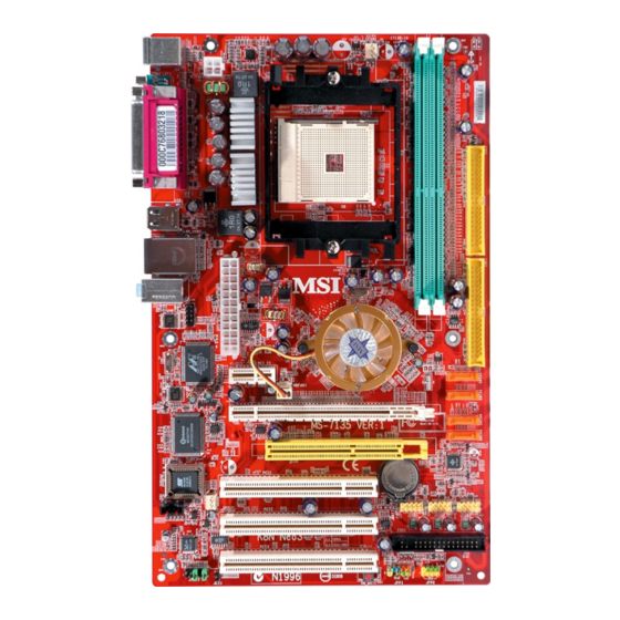
Getting Started Mainboard Layout Top: Mouse CFAN1 Bottom: Keyboard JPW1 Top: Parallel Port Bottom: COM Port USB Ports T: LAN Jack JWR1 B: USB Port s Line-In Line-Out JCOM1 nVIDIA nForce4-4X PCI_E1 SATA2 NBFAN1 PCI_E2 SATA1 SATA4 Winbond W83627THF SATA3 PCI 1 JUSB2 SFAN1... -
Page 13: Msi Special Features
BIOS/drivers version on the MSI Web site. To use the function, you need to install the “MSI Live Update 3” application. After installation, the “MSI Live Monitor” icon (as shown on the right) will appear on the screen. Double click this icon to run the application. -
Page 14: Live Bios™/Live Driver
Live Update 3” icon (as shown on the right) will appear on the screen. Double click the “MSI Live Update 3” icon, and the fol- lowing screen will appear: Several buttons are placed on the left column of the screen. Click the desired button to start the update process. -
Page 15: Core Center (For Amd K8 Processor)
MS-7135 ATX Mainboard Core Center (for AMD K8 Processor) Click on the Core Center icon in the main menu and the Core Center program will be enabled. Cool’n’Quiet This utility provides a CPU temperature detection function called Cool’n’Quiet. ® Cool’n’Quiet is a special feature designed only for AMD Athlon64 processor, and with Cool’n’Quiet, the system will be capable of detecting the temperature of the CPU according to the CPU’s working loading. - Page 16 CPU fan speed in 8 different modes, from High Speed to Low speed. If you choose Cool’n’Quiet, the system will automatically configure an optimal setting for you. MSI Reminds You... To ensure that Cool’n’Quiet function is activated and will...
-
Page 17: Packing Checklist
MS-7135 ATX Mainboard Packing Checklist MSI Driver/ Utility CD & RAID Driver Disk SATA Cable (Optional) MSI mainboard Round Cable of Round Cable of Power Cable Floppy Disk (Optional) IDE Devices (Optional) USB Bracket (Optional) Back IO Shield User’s Guide... -
Page 18: Chapter 2. Hardware Setup
Hardware Setup Chapter 2. Hardware Setup Hardware Setup This chapter tells you how to install the CPU, memory modules, and expansion cards, as well as how to setup the jumpers on the mainboard. Also, it provides the instructions on connecting the pe- ripheral devices, such as the mouse, keyboard, etc. -
Page 19: Quick Components Guide
MS-7135 ATX Mainboard Quick Components Guide CPU, p.2-3 JPW1, p.2-9 DDR DIMMs, p.2-7 CFAN1, p.2-12 Back Panel I/O, p.2-11 IDE1/2, p.2-13 JCOM1, p.2-16 JWR1, p.2-9 PCI Express SATA1~4, p.2-14 Slots, p.2-19 AGR Slot, p.2-20 J1, p.2-15 JUSB1/2/3, p.2-17 FDD1, p.2-12 PCI Slots, p.2-19 JFP2, p.2-16 JAUD1, p.2-15... -
Page 20: Central Processing Unit: Cpu
If you do not have the heat sink and cooling fan, contact your dealer to purchase and install them before turning on the computer. For the latest information about CPU, please visit http://www.msi.com.tw/pro- gram/products/mainboard/mbd/pro_mbd_cpu_support.php. MSI Reminds You... -
Page 21: Cpu Installation Procedures For Socket 754
MS-7135 ATX Mainboard CPU Installation Procedures for Socket 754 1. Please turn off the power and unplug the power cord before O pen Lever installing the CPU. Sl i di ng 90 degree Pl at e 2. Pull the lever s ideways away from the socket. -
Page 22: Installing Amd Athlon64 Cpu Cooler Set
MSI Reminds You... Mainboard photos shown in this section are for demonstration of the cooler installation for Socket 754 CPUs only. The appearance of your mainboard may vary depending on the model you purchase. - Page 23 9. Attach the CPU Fan cable to the CPU fan connector on the mainboard. MSI Reminds You... While disconnecting the Safety Hook from the fixed bolt, it is neces- sary to keep an eye on your fingers, because once the Safety Hook is...
-
Page 24: Memory
Maximum System Memory Supported 64MB~2GB S: Single Side D: Double Side MSI Reminds You... 1. Make sure that you install memory modules of the same type and density on DDR DIMMs. 2. For systems using double-sided DDR400 modules in single-chan-... -
Page 25: Installing Ddr Modules
The plastic clip at each side of the DIMM slot will automatically close. Notch Volt MSI Reminds You... You can barely s ee the golden finger if the module is properly inserted into the socket. -
Page 26: Power Supply
JPW1 Pin Definition SIGNAL JPW1 MSI Reminds You... 1. These two connectors connect to the ATX power supply and have to work together to ensure stable operation of the mainboard. 2. Power supply of 350 watts (and above) is highly recommended for system stability. -
Page 27: Important Notification About Power Issue
Figure 2: Figure 3: Unplug the JWR1 power connector Unplug the JPW 1 power connector MSI Reminds You... Mainboard photos shown in this section are for demonstration only. The appearance of your mainboard may vary depending on the model you purchase. -
Page 28: Back Panel
Hardware Setup Back Panel L-In Parallel M ou se L-Out Keyboard Serial Port USB Ports M ouse/Keyboard Connector RJ-45 LAN Jack Pin5 Mouse/KBD Clock Pin6 NC Pin4 VCC Pin3 GND Gigabit LAN (Optional) Pin1 Pin2 NC Mouse/KBD SIGNAL DESCRIPTION DATA Differential Pair 0+ Differential Pair 0- Serial Port... -
Page 29: Connectors
+12V CFAN1 SFAN1 NBFAN1 MSI Reminds You... 1. Always consult the vendors for proper CPU cooling fan. 2. CFAN1 supports Smart Fan control. You can install Core Center utility that will automatically control the CPU fan speed according to the actual CPU temperature. Alternatively, you may set up the smart fan control functions in the BIOS setup utility. -
Page 30: Ata133 Hard Disk Connectors: Ide1 & Ide2
IDE2 (Secondary IDE Connector) IDE2 can also connect a Master and a Slave drive. MSI Reminds You... If you install two hard disks on cable, you must configure the second drive to Slave mode by setting its jumper. Refer to the hard disk docu- mentation supplied by hard disk vendors for jumper setting instructions. -
Page 31: Serial Ata Connectors: Sata1~Sata4
Serial ATA cable Take out the dust cover and connect to the hard disk devices Connect to SATA1/2/3/4 MSI Reminds You... Please do not fold the Serial ATA cable into 90-degree angle. Otherwise, data loss may occur during transmission. 2-14... -
Page 32: Cd-In Connector: J1
Left channel audio signal to front panel AUD_RET_L Left channel audio signal return from front panel MSI Reminds You... If you don’t want to connect to the front audio header, pins 5 & 6, 9 & 10 have to be jumpered in order to have signal output directed to the rear audio ports. -
Page 33: Front Panel Connectors: Jfp1, Jfp2
MS-7135 ATX Mainboard Serial Port Header: JCOM1 The mainboard offers one 9-pin header as serial port. The port is a 16550A high speed communication port that sends/receives 16 bytes FIFOs. You can attach a serial mouse or other serial device directly to it. Pin Definition SIGNAL DESCRIPTION... -
Page 34: Chassis Intrusion Switch Connector: Jci1
USB1- JUSB1/2/3 USB0+ USB1+ (USB 2.0) Key (no pin) USBOC Connect to JUSB1, JUSB2, or USB 2.0 Bracket JUSB3 (Optional) MSI Reminds You... Note that the pins of VCC and GND must be connected correctly to avoid possible damage. 2-17... -
Page 35: Jumpers/Buttons
SW _BAT1 button to have the data eras ed. SW_BAT1 MSI Reminds You... You can clear CMOS by pressing this button while the system is off. Avoid clearing CMOS while the system is on; it will damage the mainboard. -
Page 36: Slots
Hardware Setup Slots The motherboard provides one PCI Express x1 slot, one PCI Express x16 slot, three 32-bit PCI slots, and one AGR slot. PCI (Peripheral Component Interconnect) Express Slots The PCI Express slots support high-bandwidth, low pin count, and serial interconnect technology. -
Page 37: Agr (Advance Graphics Riser) Slot
VGA BIOS VGA Driver MB Driver (from NVOM011 CD) MSI Reminds You... The VGA BIOS and driver versions need to be identical to the ver- sions in the compatibility list in order to have the AGR function work properly. 2-20... -
Page 38: Hardware Setup
6.14.10.6681 MS-8863 GeForce 4 MX 460 64MB/SDRAM 4.17.00.30.06 Pass 6.14.10.6681 MS-8907 GeForce FX 5200 64MB/DDR SDRAM 4.34.20.22.00 Pass 6.14.10.6681 10 MSI MS-8911 GeForce FX 5200 128MB/DDR SDRAM 4.34.20.15.00 Pass 6.14.10.6681 11 MSI MS-8919 GeForce FX 5200 128MB/DDR SDRAM 4.34.20.23.08 Pass 6.14.10.6681... -
Page 39: Pci Interrupt Request Routing
MS-7135 ATX Mainboard VGA CARD MS-7135 Model name VGA Chip VGA Memory VGA BIOS Vender SPEED Result Driver Ver. 51 MSI MS-8888 GeForce 4 MX 440 64MB/DDR SDRAM 4.18.20.03.00 Pass 6.6.8.1 52 MSI MS-8889 GeForce 4 Ti 4200 128MB/DDR SDRAM 4.28.20.05.02 Pass 6.6.8.1... -
Page 40: Chapter 3. Bios Setup
SETUP. ² You want to change the default settings for customized features. MSI Reminds You... 1. The items under each BIOS category described in this chapter are under continuous update for better system performance. -
Page 41: Entering Setup
MS-7135 ATX Mainboard Entering Setup Power on the computer and the system will start POST (Power On Self Test) process. W hen the message below appears on the screen, press <DEL> key to enter Setup. P r e s s D E L e n t e r S E T U P... -
Page 42: Getting Help
BIOS Setup Getting Help After entering the Setup menu, the first menu you will see is the Main Menu. M ain M enu The main menu lists the setup functions you can make changes to. You can use the control keys ( ↑↓ ) to select the item. The on-line description of the highlighted setup function is displayed at the bottom of the screen. -
Page 43: The Main Menu
MS-7135 ATX Mainboard The Main Menu ® Once you enter Phoenix-Award BIOS CMOS Setup Utility, the Main Menu will appear on the screen. The Main Menu allows you to select from twelve setup func- tions and two exit choices. Use arrow keys to select among the items and press <Enter>... - Page 44 BIOS Setup Cell M enu Use this menu to specify your settings for CPU/AGP frequency/voltage control and overclocking. Load Optimized Defaults Use this menu to load the default values set by the mainboard manufacturer specifi- cally for optimal performance of the mainboard. BIOS Setting Password Use this menu to set the password for BIOS.
-
Page 45: Standard Cmos Features
MS-7135 ATX Mainboard Standard CMOS Features The items in Standard CMOS Features Menu are divided into several categories. Each category includes no, one or more than one setup items. Use the arrow keys to highlight the item and then use the <PgUp> or <PgDn> keys to select the value you want in each item. - Page 46 BIOS Setup provided in the documentation from your hard disk vendor or the system manufacturer. [Access Mode] The settings are [CHS], [LBA], [Large], [Auto]. [Capacity] The formatted size of the storage device. [Cylinder] Number of cylinders. [Head] Number of heads. [Precomp] W rite precompensation.
-
Page 47: Advanced Bios Features
MS-7135 ATX Mainboard Advanced BIOS Features Quick Booting Select [Enabled] to reduce the amount of time required to run the power-on self-test (POST). A quick POST skips certain steps. We recommend that you normally disable quick POST. It is better to find a problem during POST than lose data during your work. Options: [Enabled], [Disabled]. - Page 48 1st/2nd/3rd Boot Device The items allow you to set the sequence of boot devices where BIOS attempts to load the disk operating system. MSI Reminds You... Available settings for “1st/2nd/3rd Boot Device” vary depending on the bootable devices you have installed.
-
Page 49: Advanced Chipset Features
MS-7135 ATX Mainboard Advanced Chipset Features MSI Reminds You... Change these settings only if you are familiar with the chipset. It is strongly recommended that users should leave the settings to their default options. DRAM Configuration Press <Enter> to enter the sub-menu and the following screen appears: Timing M ode This field has the capacity to automatically detect all of the DRAM timing. - Page 50 BIOS Setup set this field to [Manual], the following fields will be selectable. The settings are: [Auto], [Manual]. M emclock index value (M hz) W hen Timing Mode is set to [Manual], user can place an artificial memory clock on the system. Please note that memory is prevented from running faster than this frequency.
- Page 51 MS-7135 ATX Mainboard back, which takes twice the amount of time. W ith current DRAM chip densities, this is not yet an issue, however, with the upcoming densities of greater than 1 Gbit/chip, tRFC will have to be roughly 2 x tRC. Setting options: [Auto], [9T] ~ [24T].
- Page 52 BIOS Setup Read Preamble value W hen the User Config mode is set to [Manual], the field is adjustable. It specifies the time prior to the max-read DQS-return when the DQS receiver should be turned on. This is specified in units of 0.5ns. The controller needs to know when to enbale its DQS receiver in anticipation of the DRAM DQS driver truning on for a read.
-
Page 53: Integrated Peripherals
MS-7135 ATX Mainboard Integrated Peripherals USB Controller This setting allows you to enable/disable the onboard USB controller. Selecting [Enabled] enables the system to support both USB 1.1 and 2.0 spec. Setting options: [Disabled], [Enabled]. USB KB/Storage Support Select [Enabled] if you need to use a USB-interfaced keyboard or storage device in the operating system. - Page 54 BIOS Setup I/O Device Configuration Press <Enter> to enter the sub-menu and the following screen appears: Onboard FDC Controller Select [Enabled] if your system has a floppy disk controller (FDD) installed on the system board and you wish to use it. If you install add-on FDC or the system has no floppy drive, select [Disabled] in this field.
- Page 55 MS-7135 ATX Mainboard EPP M ode Select The onboard parallel port is EPP Spec. compliant, so after the user chooses the onboard parallel port with the EPP function, the following message will be displayed on the screen: “EPP Mode Select.” At this time either [EPP 1.7] spec or [EPP 1.9] spec can be chosen.
- Page 56 BIOS Setup SATA Device Configuration Press <Enter> to enter the sub-menu and the following screen appears: RAID Enable This item is used to enable/disable the onchip RAID function. W hen you set to [Enabled], the following fields will become selectable. Setting options: [Enabled], [Disabled].
-
Page 57: Power Management Setup
MS-7135 ATX Mainboard Power Management Setup MSI Reminds You... S3-related functions described in this section are available only when your BIOS supports S3 sleep mode. ACPI Standby State This item specifies the power saving modes for ACPI function. If your operating... - Page 58 BIOS Setup Power Button Function This feature sets the function of the power button. Settings are: [Power Off] The power button functions as normal power off button. [Suspend] W hen you press the power button, the computer enters the suspend/sleep mode, but if the button is pressed for more than four seconds, the computer is turned off.
- Page 59 The field specifies the time for Resume By RTC Alarm. Format is <hour> <minute><second>. MSI Reminds You... If you have changed this setting, you must let the system boot up until it enters the operating system, before this function will work.
-
Page 60: Pnp/Pci Configurations
BIOS Setup PNP/PCI Configurations This section describes configuring the PCI bus system and PnP (Plug & Play) feature. PCI, or Peripheral Component Interconnect, is a system which allows I/O devices to operate at speeds nearing the speed the CPU itself uses when communi- cating with its special components. - Page 61 MS-7135 ATX Mainboard ** PCI Express Relative Items ** M aximum Payload Size This setting specifies the maximum TLP payload size for the PCI Express devices. The unit is byte. Setting options: [128], [256], [512], [1024], [2048], [4096]. 3-22...
-
Page 62: H/W Monitor
BIOS Setup H/W Monitor This section shows the status of your CPU, fan, overall system status, etc. Monitor function is available only if there is hardware monitoring mechanism onboard. Chassis Intrusion Detect The field enables or disables the feature of recording the chassis intrusion status and issuing a warning message if the chassis is once opened. - Page 63 MS-7135 ATX Mainboard Current Sy stem/CPU Temperature, Sy stem/CPU/Northbridge Fan Speed, CPU Vcore, +3.3V, +5.0V, Battery, +5VSB These items display the current status of all of the monitored hardware de- vices/components such as CPU voltage, temperatures and all fans’ speeds. 3-24...
-
Page 64: Cell Menu
Dynamic Overclocking Dynamic Overclocking Technology is the automatic overclocking function, included in ’s newly developed CoreCell the MSI Technology. It is designed to detect the load balance of CPU while running programs, and to adjust the best CPU frequency automatically. W hen the motherboard detects CPU is running programs, it will speed up CPU automatically to make the program run smoothly and faster. - Page 65 5th level of overclocking, increasing the CPU frequency by 9%. [Commander] 6th level of overclocking, increasing the CPU frequency by 11%. MSI Reminds You... 1. Even though the Dynamic Overclocking Technology is more stable than manual overclocking, basically, it is still risky. We suggest that users should make sure that the CPU can afford to overclocking regularly first.
- Page 66 This feature is especially designed for AMD Athlon processor, which provides a CPU temperature detecting function to prevent your CPU’s from overheating due to heavy workload. Setting options: [Disabled], [Enabled]. MSI Reminds You... To ensure the stability of Cool'n'Quiet function, it is always recom- mended to have the memories plugged in DIMM1.
- Page 67 MS-7135 ATX Mainboard NF4 Voltage NF4 voltage is adjustable in this field. MSI Reminds You... The settings shown in different color in Memory Voltage and NF4 Voltage help to verify if your setting is proper for your system. G ray: Default setting.
-
Page 68: Bios Setting Password
BIOS Setup Load Optimized Defaults The Optimized Defaults are the default values set by the mainboard manufac- turer specifically for optimal performance of the mainboard. W hen you select Load Optimized Defaults, a message as below appears: Pressing [Y] loads the default factory settings for optimal system performance. BIOS Setting Password W hen you select this function, a message as below will appear on the screen: Type the password, up to 8 characters in length, and press <Enter>. -
Page 69: Chapter 4. Introduction To Digicell
MP3 files management and com- munication / 802.11g W LAN settings. Moreover, with this unique utility, you will be able to activate the MSI well-known features, Live Update and Core Center, which makes it easier to update the BIOS/drivers online, and to monitor the system hardware status (CPU/Fan tem- perature and speed) or to overclock the CPU/memory. -
Page 70: Main
Introduction: Click on each icon appearing above to enter the sub-menu to make further configuration. M SI Click on this button to link to MSI website: http://www.msi.com.tw. Quick Guide Click on this button and the quick guide of DigiCell will be displayed for you to review. - Page 71 Power on Agent In this sub-menu, you can configure date, time and auto-executed programs of the power-on, power-off and restarting features. MSI Reminds You... Click on back button in every sub-menu and it will bring you back to the main menu.
-
Page 72: H/W Diagnostic
In the H/W Diagnostic sub-menu, you can see the information, status and note of each DigiCell. You may double check the connection and installation of the item marked as gray. You may also click on the Mail to MSI button to send your questions or suggestions to MSI’s technical support staff. -
Page 73: Communication
Introduction to DigiCell Communication In the Communication sub-menu, you can see the status of all the LAN / W LAN / Bluetooth on the screen if the hardware is installed. The first icon indicates the onboard LAN on your system, the second icon indicates the wireless LAN status, and the third one is the information about the bluetooth on your system. -
Page 74: Software Access Point
MS-7135 ATX Mainboard M SI Feature Software Access Point In the Software Access Point sub-menu, you can see the communication status on your system and choose the desired software access point mode by clicking on the desired icon, in which the default settings are configured for your usage. The default software access point mode is set to WLAN Card M ode. -
Page 75: Access Point Mode
Introduction to DigiCell Access Point Mode Click on “Setting” button of the Access Point Mode and the following screen will display. IP Sharing Click on this icon to enable/disable the IP sharing. The default of this setting is disabled. Disabled. Enabled. -
Page 76: Wlan Card Mode
MS-7135 ATX Mainboard M SI Feature can connect to the wireless LAN. M AC Address MAC stands for Media Access Control. A MAC address is the hardware address of a device connected to a network. Security This option allows you to enable/disable the authentication function. Authentication Open: Communicates the key across the network. -
Page 77: Live Update
BIOS/drivers/VGA BIOS/VGA Driver/Utility online so that you don’t need to search for the correct BIOS/driver version throughout the whole Web site. To use the function, you need to install the “MSI Live Update 3” application. After the installation, the “MSI Live Update 3”... -
Page 78: Mega Stick
MS-7135 ATX Mainboard M SI Feature MEGA STICK In the MEGA STICK sub-menu, you can configure the settings of MSI MEGA STICK and the media files (*.m3u, *.mp3, *.wav, *.cda, *.wma) on your system. Basic Function Here you can edit your own play list with the buttons “load”, “save”, “delete”, “shuttle”, “repeat”... - Page 79 Introduction to DigiCell There is also a toolbar for you to execute some basic function, like play, stop, pause, previous/next song, song info and volume adjust. There is also a scroll bar on the top for you to forward/rewind. pause previous next forward/rewind...
-
Page 80: Non-Unicode Programs Supported
MS-7135 ATX Mainboard M SI Feature Non-Unicode programs supported If you are using an operating system in European languages, and you’d like to play the media files in MEGA STICK with East-Asian languages (such as Chinese, Japanese... etc.), it is possible that the file names display incorrectly. However, you can ins tall the Supplemental Language Support provided by Microsoft to solve this problem. - Page 81 Introduction to DigiCell 3. Then go to the [Advanced] tab and select the language you want to be supported (the language of the filename in the MegaStick) from the drop- down list in the [Language for non-Unicode programs], then click [Apply]. The system will install the necessary components from your Microsoft Setup CD immediately.
-
Page 82: Core Center (For Amd K8 Processor)
MS-7135 ATX Mainboard M SI Feature Core Center (for AMD K8 Processor) Click on the Core Center icon in the main menu and the Core Center program will be enabled. Cool’n’Quiet This utility provides a CPU temperature detection function called Cool’n’Quiet. ®... - Page 83 CPU fan speed in 8 different modes, from High Speed to Low speed. If you choose Cool’n’Quiet, the system will automatically configure an optimal setting for you. MSI Reminds You... To ensure that Cool’n’Quiet function is activated and will...
-
Page 84: Audio Speaker Setting
MS-7135 ATX Mainboard M SI Feature Audio Speaker Setting In the Audio Speaker Setting sub-menu, you can configure the multi-channel audio operation, perform speaker test, and choose the environment you prefer while en- joying the music. You can scroll the bar of each equalizer to regulate the current playing digital sound source. - Page 85 Introduction to DigiCell Click on the “Speaker test” button and the following dialogue box will appear: In this Speaker Configuration dialogue box, select the audio configuration which is identical to the audio jack on your mainboard. Once the correct audio configuration is selected, click “Apply”...
-
Page 86: Power On Agent
Click “OK” to restart the computer right away or click “Later” to restart your computer later. MSI Reminds You... Please note that the new setting will not take effect until you restart your computer. -
Page 87: Power Off / Restart
Delete. delete the added program MSI Reminds You... You can also enable the Every turn on function, which will enable the specified program(s) and file(s) every time the Digi Cell utility runs. -
Page 88: Auto Login
MS-7135 ATX Mainboard M SI Feature Auto Login Since the Power On function allows the system to power on automatically, you may have to enable this Auto Login function in the following situations: 1. If you are using a computer belonging to a domain in office, and you need to enter your user name &... -
Page 89: Appendix A: Using 2-, 4- & 6-Channel Audio Function
Using Audio Function Appendix A: Using 2-, 4- & 6-Channel Audio Function The mainboard is equipped with Realtek ALC655 chip, which provides support for 6-channel audio output, including 2 Front, 2 Rear, 1 Center and 1 Subwoofer channel. ALC655 allows the board to attach 4 or 6 speakers for better surround sound effect. -
Page 90: Installing The Audio Driver
2. Click Realtek AC97 Audio Drivers. Clic k he r e MSI Reminds You... The AC97 Audio Configuration s o f t w a r e u t ilit y is u n d e r continuous update to enhance audio applications. Hence, the program screens shown here in this appendix may be slightly different from the latest software utility and shall be held for reference only. - Page 91 Using Audio Function 3 . Click Next to install the AC’97 Audio software. Clic k he r e 4 . Click Finish to restart the system. Se le ct this o ptio n Clic k he r e...
-
Page 92: Software Configuration
MS-7135 ATX Mainboard Software Configuration After installing the audio driver, you are able to use the 2-/4-/6-channel audio feature now. Click the audio icon from the window tray at the lower-right corner of the screen to activate the AC97 Audio Configuration. Sound Effect Here you can select a sound effect you like from the Environment list. - Page 93 Using Audio Function Here it provides the Karaoke function which will automatically remove human voice (lyrics) and leave melody for you to sing the song. Note that this function applies only for 2-channel audio operation. Just check the Voice Cancellation box and then click OK to activate the Karaoke function.
-
Page 94: Equalizer
MS-7135 ATX Mainboard Equalizer Here you regulate each equalizer for current playing digital sound sources. You may choose the provided sound effects, and the equalizer will adjust automatically. If you like, you may also load an equalizer setting or make an new equalizer setting to save as an new one by using the buttons Load and Save. -
Page 95: Speaker Configuration
Using Audio Function Speaker Configuration In this tab, you can easily configure your multi-channel audio function and speakers. Select a desired multi-channel operation from Number of Speakers. a. Headphone for the common headphone b. 2-Channel Mode for Stereo-Speaker Output c. 4-Channel Mode for 4-Speaker Output d. -
Page 96: Speaker Test
MS-7135 ATX Mainboard Speaker Test You can use this tab to test each connected speaker to ensure if 4- or 6- channel audio operation works properly. If any speaker fails to make sound, then check whether the cable is inserted firmly to the connector or replace the bad speakers with good ones. - Page 97 Using Audio Function MSI Reminds You... 1. 6 speakers appear on the “Speaker Test” tab only when you select “6-Channel M ode” in the “Number of Speak ers” c olumn in “Speaker Configuration” tab. If you select “4-Channel Mode”, only 4 speakers appear on the window.
-
Page 98: Hrtf Demo
MS-7135 ATX Mainboard HRTF Demo In this tab you may adjust your HRTF (Head Related Transfer Functions) 3D positional audio before playing 3D audio applications like gaming. You may also select different environment to choose the most suitable environment you like. A-10... -
Page 99: General
Using Audio Function General In this tab it provides some information about the AC97 Audio Configuration utility, including Audio Driver Version, DirectX Version, Audio Controller & AC97 Codec. You may also select the language of this utility by choosing from the Language list. A-11... -
Page 100: Using 2-, 4- & 6- Channel Audio Function
MS-7135 ATX Mainboard Using 2-, 4- & 6- Channel Audio Function In addition to a default 2-channel analog audio output function, the audio connectors on the Back Panel also provide 4- or 6-channel analog audio output function if a proper setting is made in the software utility. Read the following steps to have the Multi-Channel Audio Function properly set in the software utility, and have your speakers correctly connected to the Back Panel. - Page 101 Using Audio Function n 4-Channel M ode for 4-Speaker Output The audio jacks on the back panel always provide 2-channel analog audio output function, however these audio jacks can be transformed to 4- or 6- channel analog audio jacks by selecting the corresponding multi-channel operation from No.
- Page 102 * Both Line In and MIC function are converted to Line Out function when 6-Channel Mode for 6-Speaker Output is selected. MSI Reminds You... While you are testing the speakers in 6-Channel Mode, if the sound coming from the center speaker and subwoofer is swapped, you should select Swap Center/Subwoofer Output to readjust these two channels.
-
Page 103: Appendix B: Nvidia Raid Introduction
nVIDIA RAID Introduction Appendix B: nVIDIA RAID Introduction NVIDIA brings Redundant Array of Independent Disks (RAID) technology— which is used by the world’s leading businesses—to the common PC desktop. This technology uses multiple drives to either increase total disk space or to offer data protection. -
Page 104: Introduction
MSI Reminds You... Please note that the companion MSI Driver/Utility CD supports this mainboard with Windows 2000/XP system drivers ONLY. Hence, users cannot install OS, either WinME or Win98, in their SATA hard drives. -
Page 105: Basic Configuration Instructions
nVIDIA RAID Introduction RAID Configuration Basic Configuration Instructions The following are the basic steps for configuring NVRAID: Non-Bootable RAID Array 1. Choose the hard disks that are to be RAID enabled in the system BIOS. (Check p. 3-17 for details.) 2. - Page 106 Channel 2, controller 0, Master 2.1.M Channel 2, controller 1, Master MSI Reminds You... There is no such thing as Slave drive in Serial ATA. All drives are considered to be Master since there is a one to one connection...
- Page 107 nVIDIA RAID Introduction Using the Define a New Array Window If necessary, press the tab key to move from field to field until the appropriate field is highlighted. • Selecting the RAID Mode By default, this is set to [Mirroring]. To change to a different RAID mode, press the down arrow key until the mode that you want appears in the RAID Mode box—either [Mirroring], [Striping], [Spanning], or [Stripe Mirroring].
- Page 108 MS-7135 ATX Mainboard Completing the RAID BIOS Setup 1. After assigning your RAID array disks, press F7. The Clear disk data prompt appears. 2. Press Y if you want to wipe out all the data from the RAID array, otherwise press N.
-
Page 109: Installing The Nvidia Raid Software Under Windows
nVIDIA RAID Introduction NVIDIA RAID Utility Installation Installing the NVIDIA RAID Software Under Windows (for Non-bootable RAID Array) The existing W indows IDE Parallel ATA driver (as well as the Serial ATA driver if SATA is enabled) must be upgraded to use the NVIDIA IDE Parallel ATA driver (as well as the NV Serial ATA driver if SATA is enabled). -
Page 110: Installing The Raid Driver (For Bootable Raid Array
Please follow the instruction below to make an nVIDIA RAID driver for yourself. 1. Insert the MSI CD into the CD-ROM drive. 2. Ignore the Setup screen and use “Explorer” to browse the CD. 3. Copy all the contents (excluding the subfolders) in the \\nVidia\System\CK804\IDE\WinXP or \\nVidia\System\CK804\IDE\Win2K to a formatted floppy disk. - Page 111 This will not be an issue with a signed driver. MSI Reminds You... Each time you add a new hard drive to a RAID array, the RAID driver will have to be installed under Windows once for that hard drive. After...
-
Page 112: Initializing And Using The Disk Array
MS-7135 ATX Mainboard Initializing and Using the Disk Array The RAID array is now ready to be initialized under W indows. 1. Launch Computer Management by clicking “Start” --> “Settings” --> “Control Panel” --> “Switch to Classic View” then open the “Administrative Tools” folder and double click on “Computer Management”. - Page 113 nVIDIA RAID Introduction 5. Check the disk in the list if you want to make the array a dynamic disk, then click Next. The Completing the Initialize and Convert Disk Wizard window appears. 6. Click Finish. The “Computer Management” window appears. The actual disks listed will depend on your system, and the unallocated partition is the total combined storage of two hard disks.
-
Page 114: Raid Drives Management
\\nVidia\System\CK804\IDE\Win2K\raidtool of the setup CD accompanied with your mainboard). The RAID configuration information appears in the right-side pane, as shown below. MSI Reminds You... The information in the figures in this part may very from what it is shown in your system. - Page 115 nVIDIA RAID Introduction NVRAID Striped Array The figure below shows an example of a two hard drive striped array using identical 55.90 GB IDE hard drives (ST360015A), where one drive is configured as Master and the other drive is configured as Slave. The total disk space used is 111.80 GB. NVRAID Striped Mirror Array The figure below shows an example of a four hard drive stripe-mirrored array.
-
Page 116: Setting Up A Spare Raid Disk
MS-7135 ATX Mainboard Setting Up a Spare RAID Disk You can designate a hard drive to be used as a spare drive for a RAID 1 or RAID 0+1 array2. The spare drive can take over for a failed disk. NVRAID supports two types of spare drives: •... - Page 117 nVIDIA RAID Introduction Assigning a Dedicated Disk To mark a disk as dedicated, or reserve it for use by a specific array, Step 1: Mark the Disk as a Free Disk 1. Enter the system BIOS setup and make sure that the drive that you want to mark as free is RAID enabled.
- Page 118 MS-7135 ATX Mainboard 3. Click Next. The RAID Array Selection page appears. 4. From the RAID Array Selection page, select one of the arrays from the list. This is the array to which you want to allocate the dedicated free disk. Note: There is only one array created on the system.
- Page 119 nVIDIA RAID Introduction M ethod 2: Select an array and then assign a free disk to it. 1. Right click on the array to which you want to assign a dedicated free disk. The pop- up menu appears. 2. Select Designate Spare from the menu to launch the Spare Disk Allocation Wizard. 3.
- Page 120 MS-7135 ATX Mainboard 5. Click Next. The Completing the NVIDIA Spare Disk Allocation page appears. 6. Click Finish. You have now assigned a dedicated free disk to a mirrored array. Once a dedicated disk has been assigned to a particular array, it can be removed at any time.
- Page 121 nVIDIA RAID Introduction Example of Dedicating a Free Disk in a RAID 1 or RAID 0+1 Array You can also assign a dedicated free disk to a RAID 1 or a RAID 0+1 array, using the same process. 1. Right-click either the free disk that you want to dedicate to an array, the array type, or the array drives as shown in the figure below.
-
Page 122: Rebuilding A Raid Mirrored Array
MS-7135 ATX Mainboard Rebuilding a RAID Mirrored Array Rebuilding is the process of recovering data from one hard drive to another. All data is copied from one hard drive to another and then the data is synchronized between the two hard drives. This only applies to RAID 1 array as well as a RAID 0+1 array. Rebuilding Instructions After creating a mirrored array, you can rebuild the array using the following steps: 1. - Page 123 nVIDIA RAID Introduction 4. Click Next. The Disk Selection page appears. 5. Select the drive that you want to rebuild by clicking it from the list, then click Next. The Completing the NVIDIA Rebuild Array page appears. 6. Click Finish. The array rebuilding starts after a few seconds, and a small pop-up message appears towards the bottom right corner of the screen as shown in the figure below.
- Page 124 MS-7135 ATX Mainboard M ore About Rebuilding Arrays • Rebuilding Occurs in the Background The rebuilding process is very slow (it can take up to a day) and occurs in the background so as not to affect the performance of the system. •...
Need help?
Do you have a question about the K8N Neo3 MS-7135 and is the answer not in the manual?
Questions and answers