Epson TM-U325D Operator's Manual
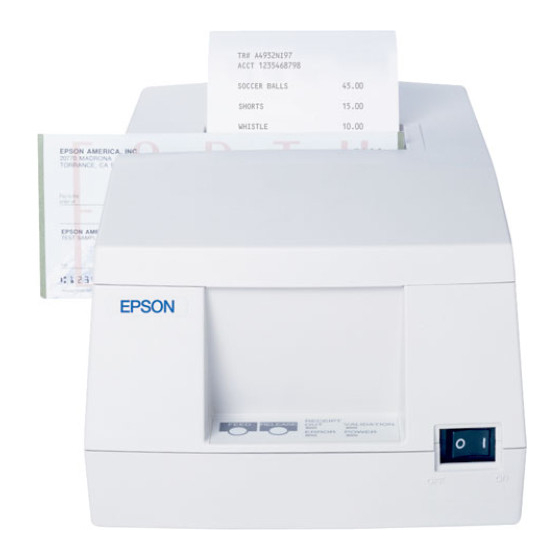
Validation/receipt printer
Hide thumbs
Also See for TM-U325D:
- User manual (63 pages) ,
- Specifications (2 pages) ,
- User manual (57 pages)
Table of Contents
Advertisement
Quick Links
See also:
User Manual
TM-U325D/U325PD
Operator's Manual
Using this online technical guide
The words on the left side of this screen are bookmarks for all the
topics in this guide.
Use the scroll bar next to the bookmarks to find any topic you
want. Click a bookmark to instantly jump to its topic. (If you wish,
you can increase the size of the bookmark area by dragging the
dividing bar to the right.)
Use the scroll bar on the right side of this screen to move
through the text.
Use the zoom tools to magnify or reduce the page display.
Click the Find button if you want to search for a particular term.
(However, using the bookmarks is usually quicker.)
Complete online documentation for Acrobat Reader is located in the Help directory for Acrobat Reader.
Return to main menu
Advertisement
Table of Contents

Related Manuals for Epson TM-U325D


Summary of Contents for Epson TM-U325D
- Page 1 TM-U325D/U325PD Operator’s Manual Using this online technical guide The words on the left side of this screen are bookmarks for all the topics in this guide. Use the scroll bar next to the bookmarks to find any topic you want. Click a bookmark to instantly jump to its topic. (If you wish, you can increase the size of the bookmark area by dragging the dividing bar to the right.)
- Page 2 Validation/Receipt Printer TM-U325D/U325PD Operator’s Manual 400665700...
- Page 3 Parallel interface connector Control panel Control panel RECEIPT On/Off switch VALIDATION FEED RELEASE ERROR POWER EPSON/U325 Printer - File: PRNT W. Swanlund REV> 14O Labels CLOSE THE PRINTER COVER CAUTION: Caution labels for drawer kick-out connector and print head cover.
-
Page 4: Quick Reference
Quick Reference This Quick Reference will direct you to key areas of this Operator’s Manual. For a complete listing of topics, see the Contents. Printer Parts and Labels inside front cover Ordering Ribbons page vii Where to order ribbons. Setting Up the Printer page 1-1 How to set up the printer. - Page 5 Seiko Epson Corporation. No patent liability is assumed with respect to the use of the information contained herein. While every precaution has been taken in the preparation of this book, Seiko Epson Corporation assumes no responsibility for errors or omissions.
-
Page 6: Fcc Compliance Statement
FCC CLASS A FCC Compliance Statement For American Users This equipment has been tested and found to comply with the limits for a Class A digital device, pursuant to Part 15 of the FCC Rules. These limits are designed to provide reasonable protection against harmful interference when the equipment is operated in a commercial environment. -
Page 7: Emi And Safety Standards Applied
EMI and Safety Standards Applied The following standards are applied only to the printers that are so labeled. (EMC is measured using Seiko Epson’s AC adapter provided with the printer. ) North America: EMI: FCC Class A Safety standards: UL 1950-2TH-D3... -
Page 8: About This Manual
Chapter 2 contains information on using the printer. Chapter 3 contains troubleshooting information. Reference Chapter 4 contains specifications and character code tables. The Appendix lists the EPSON Sales Subsidiaries and their addresses. Warnings, Cautions, and Notes WARNING: Warnings must be followed carefully to avoid serious bodily injury. - Page 9 Introduction Features The TM-U325D and TM-U325PD are high-quality POS printers that can print a mutiple-line validation and on receipt paper (paper roll). The printer has the following features: Easily changeable interface specifications for serial or parallel by exchanging the interface board.
- Page 10 Printer fastening tape (Model No. DF-10) Ordering the Ribbon Cassette The TM-U325D/U325PD uses a long-lasting ribbon cassette. To order ribbon cassettes, contact your dealer or your local affiliate. See the Appendix for a list of EPSON subsidiaries with their addresses and telephone numbers. Introduction vii...
-
Page 11: Setting Up The Printer
Chapter 1 Setting Up the Printer Unpacking When you unpack the TM-U325D or TM-U325PD printer, make sure you have these items. Power supply Printer Paper roll Manual Ribbon cassette Spacers for the paper roll Power switch cover near-end sensor 2 pcs If any item is missing or damaged, please contact your dealer for assistance. -
Page 12: Selecting A Location
Selecting a Location Place the printer on a surface that is as horizontal as possible. Make sure that the printer does not tilt more than 15 degrees. The printer should be installed so that is does not move or vibrate during paper cutting or the drawer kick-out operation. - Page 13 2. Two spacers are included. See the illustration below and decide whether or not you want to use them. Use them if you want the near-end sensor to be triggered when distance A is 3 to 4 mm; otherwise it will be triggered when distance A is approximately 6 mm.
-
Page 14: Connecting The Cables And Grounding The Printer
Connecting the Cables and Grounding the Printer You can connect up to three cables and a grounding wire to the printer. They all connect to the connector panel on the bottom of the printer, which is shown below: Power supply Drawer kick-out Grounding screws Interface... - Page 15 Connecting the Drawer WARNING: Use a drawer that matches the printer specification. Using an improper drawer may damage the drawer as well as the printer. CAUTION: Do not connect a telephone line to the drawer kick-out connector; otherwise the printer and the telephone line may be damaged.
- Page 16 Anschließen der Lade WARNUNG: Eine für den Drucker geeignete Lade verwenden. Bei Verwendung einer falschen Lade kann diese oder der Drucker beschädigt werden. ACHTUNG: Kein Telefonkabel an die Schnappsteckerbuchse anschließen, da sonst der Drucker und die Telefonkabel beschädigt werden können. Das Kabel der Lade an die Schnappsteckerbuchse unten am anschlie Drucker neben dem Netßzanschluß...
- Page 17 Grounding the Printer You need a ground wire to ground your printer. Make sure that the wire meets the specifications below. Thickness of wire: AWG 18 or equivalent Diameter of terminal to be attached: 1. Make sure that the printer is turned off. 2.
- Page 18 Connecting the Power Supply This printer requires an external power supply. Be sure to use a power supply that matches the specifications. WARNING: Using an incorrect power supply may cause fire or electrical shock. CAUTIONS: When connecting or disconnecting the power supply from the printer, make sure that the power supply is not plugged into an electrical outlet;...
-
Page 19: Installing The Ribbon Cassette
Installing the Ribbon Cassette Use the EPSON ERC-38(P) or ERC-38(B) ribbon cassette for your printer. Note the label inside the printer cover that can assist you in installing the ribbon. - Page 20 4. Insert the ribbon in the position shown in the illustration on the next page and push the ribbon cassette until it clicks. Note: Make sure that the ribbon is installed between the print head and the platen without wrinkles or creases. 5.
-
Page 21: Installing The Paper Roll
Installing the Paper Roll Notes: Be sure to use a paper roll that meets the specifications. Do not use paper rolls that have the paper glued to the core because the printer cannot detect the paper end correctly. However, if you will stop the printing using the paper roll near-end sensor, you can use glued type paper rolls. - Page 22 Note: Be sure to note the correct direction that the paper comes off the roll as shown below. 4. Hold both edges of the paper and insert it straight into the paper slot. The printer feeds the paper automatically. 1–12 Setting Up the Printer...
- Page 23 5. Tear off the paper; then close the cover. Note: Before closing the cover, make sure that the paper from the paper roll is not slack. Setting Up the Printer 1–13...
-
Page 24: Running The Self Test
To remove the paper roll, follow the steps below. 1. Open the printer cover. 2. Pull up the paper and cut the paper at the dotted line shown in the illustration below. Cut here 3. Remove the paper roll from the printer. 4. -
Page 25: Setting The Dip Switches
2. The printer prints the current printer settings and then the RECEIPT OUT light blinks to indicate that the printer is in the test printing standby state. 3. Press the FEED button to start the second part of the test, in which the printer prints a pattern using the built-in character set. - Page 26 2. Turn the printer over and remove the DIP switch access cover, as shown below. DSW1 DSW2 3. There are two sets of switches. Notice that ON is marked on each set of switches. Use tweezers or another narrow tool to move the switches.
- Page 27 Serial Interface (TM-U325D) These are the settings for printers equipped with a serial interface. DIP Switch Set 1 Switch Function Data reception error Ignored Prints”?” Receive buffer capacity 45 bytes 4K bytes Handshaking XON/XOFF DTR/DSR Word length 7 bits 8 bits...
- Page 28 DIP Switch Set 2 Switch Function Off line or receive Handshaking (BUSY Receive buffer full buffer full condition) Not defined — — Select number of characters per line 42CPL/35CPL 40CPL/33CPL (CPL) 7 × 9 font/9 × 9 font 2-4, 2-5 Not defined —...
- Page 29 Parallel Interface (TM-U325PD) These are the settings for printers equipped with a parallel interface. DIP Switch Set 1 Switch Function Auto line feed Enabled Disabled Receive buffer capacity 45 bytes 4K bytes 1-3~1-8 Not defined — — DIP Switch Set 2 Switch Function Off line or receive...
-
Page 30: Using The Power Switch Cover
5. Replace the DIP switch cover and secure it with the screw. Using the Power Switch Cover WARNING: If an accident occurs when the power switch cover is attached, unplug the power supply cord from the outlet immediately; otherwise the printer may be damaged. You can use the provided power switch cover to protect the power switch from accidental or improper operation. - Page 31 Affixing the Fastening Tape (Option) Two sets of tape are included as an option to fasten your printer to a countertop or other surface. Follow the steps below: 1. Clean the countertop or other surface where the printer will be installed.
-
Page 32: Using The Printer
Chapter 2 Using the Printer Operating the Control Panel You can feed or release paper with the buttons on the control panel. The indicator lights help you monitor the printer’s status. RECEIPT VALIDATION FEED RELEASE ERROR POWER Switch The power switch on the front of the printer turns the printer on and off. -
Page 33: Indicator Lights
The power switch and FEED button can also be used to start the self test. Indicator lights The control panel lights provide information on printer conditions. POWER (Green) The POWER light is on when the printer power is on. RECEIPT OUT (Red) This light is on when the paper roll is at the end or near the end. - Page 34 If the printer stops working and the ERROR light is blinking, turn the printer off, check for jammed paper, and remove the paper by following the instructions on page 3-3, if necessary. Then turn the printer back on. If the printer still does not work, unplug the power supply cord from the outlet immediately, and contact a qualified service person.
-
Page 35: Validation Paper Handling
Validation Paper Handling Notes: Use only validation paper that matches the printer’s specifications. See Paper Specifications in Chapter 4. Be sure that a paper roll is loaded before you use validation paper. Be sure that the validation paper is flat, without curls, folds, or wrinkles. -
Page 36: Troubleshooting
Chapter 3 Troubleshooting Troubleshooting This chapter gives solutions to some of the more common printer problems. General problems The lights on the control panel do not come on. Make sure that the power supply cords are correctly plugged into the printer, the power unit, and to the power outlet. Make sure that power is supplied to the power outlet. - Page 37 The ERROR light is off, but nothing is printed. Try to run the self test to check that the printer works properly. See the self test instructions in Chapter 1 to run the self test. If the self test does not work, contact your dealer or a qualified service person.
- Page 38 A line of dots is missing in the printout. The print head may be damaged. Stop printing and contact your dealer or a qualified service person. Removing jammed paper Follow these steps to clear a paper jam: CAUTION: The print head becomes very hot during printing. Allow it to cool before you reach into the printer.
- Page 39 5. Loosen the screw on the print head cover as shown below. 6. Lift up the print head cover. 7. Remove all the jammed paper. Note: Do not pull the jammed paper in the opposite direction of paper feeding. 8. Replace the print head cover and secure it with the screw. 3-4 Troubleshooting...
-
Page 40: Hexadecimal Dump
9. Replace the ribbon cassette and paper roll; then close the printer cover. Hexadecimal Dump This feature allows experienced users to see exactly what data is coming to the printer. This can be useful in finding software problems. When you turn on the hex dump function, the printer prints all commands and other data in hexadecimal format along with a guide section to help you find specific commands. - Page 41 Note: Insufficient print data to fill the last line can be printed by setting the printer off-line. 3-6 Troubleshooting...
-
Page 42: Reference Information
Chapter 4 Reference Information Printing Specifications Printing Method: Serial impact dot-matrix 9-pin serial configuration Head wire configuration: Printing Direction: Bi-directional, logic-seeking Characters/line See table on page 4-2. (default): Character spacing See table on page 4-2. (default) Fonts A and B: Approx. -
Page 43: Character Specifications
Character Specifications Number of Alphanumeric characters: 95 characters Extended graphics: 128 x 8 pages, International characters: 32 Character structure: 7 x 9 (the total number of dots for each horizontal line: 400 in half dot units) 9 x 9 (the total number of dots for each horizontal line: 400 in half dot units) Character size: See table below. -
Page 44: Paper Specifications
Paper Specifications Paper feed method: Friction feed Paper feed pitch: Default 1/6 inch Can be set in units of 1/144 inch by commands. Paper feed speed: Approx. 4.17 inches/second (25 lines/ second) (continuous feeding) Paper size and weight: Paper roll: Normal paper (single-ply) Size: Width 76 mm ±... - Page 45 Pressure sensitive paper Maximum 1 original + 2 copies Size: Width 76 mm ± 0.5 mm (3.0" ± 0.02") Maximum 83 mm (3.27") outside dia: Thickness: 0.05 to 0.08 mm (.0020 to .0031") (Total thickness should be a 0.2 mm or less and each sheet should be 0.05 to 0.08 mm.) Recommend...
- Page 46 Validation paper: Normal, pressure sensitive, and carbon copy paper 135 mm × 70 mm(minimum) to 182 Paper size (W × L): mm × 182 mm (maximum) (5.31” × 2.76” to 7.17” × 7.17”) (maximum 9 lines at 4.23 mm (.17”) pitch) Single-ply 0.09 mm to 0.12 mm (.0035”...
- Page 47 Copy capability Copy capability is greatly influenced Paper roll and validation by the ambient temperature, so paper: printing must be performed under the conditions described in the table below. Relationship between ambient temperature and number of copies Paper roll and validation paper: Number of copies Ambient temperature Original + 2 copies...
-
Page 48: Electrical Specifications
Validation paper with holes (e.g., sprocket holes) within the areas shown below must not be used. Otherwise, the paper cannot be detected by the paper sensor. Translucent paper must not be used. : Holes are prohibited in this area 7mm (.28") Inserting direction 11mm (.43") Electrical Specifications... - Page 49 Reliability Life: 20,000,000 lines End of Life is defined as the point at which the printer reaches the beginning of the Wearout Period. MTBF: 180,000 hours Failure is defined as Random Failure occurring at the time of the Random Failure Period. MCBF: 49,000,000 lines This is an average failure interval...
-
Page 50: Environmental Conditions
Environmental Conditions Temperature Operating 0 to 50 ° C (32 to 122 ° C) (when the temperature is 30 ° C or more, there is a limitation for the humidity. Refer to the figure below.) –10 to 50 ° C (14 to 122° F) Storage (except for paper, and a ribbon) Humidity... -
Page 51: Character Code Tables
Character Code Tables SP in a table represents space. Page 0 (PC437: U.S.A., Standard Europe) (International character set: U.S.A) 4-10 Reference Information... - Page 52 Page 1 (Katakana) Reference Information 4-11...
- Page 53 Page 2 (PC850: Multilingual) 4-12 Reference Information...
- Page 54 Page 3 (PC860: Portuguese) Reference Information 4-13...
- Page 55 Page 4 (PC863: Canadian-French) 4-14 Reference Information...
- Page 56 Page 5 (PC865: Nordic) Reference Information 4-15...
- Page 57 Page 254 (Space Page) 4-16 Reference Information...
- Page 58 Page 255 (Space Page) Reference Information 4-17...
-
Page 59: International Character Set
International character set ASCII code (hexadecimal) Country U.S.A. ¦ à ° ç § é ù è ¨ France Germany § Ä Ö Ü ä ö ü ß U.K. £ ¦ Denmark I Æ Ø Å æ ø å Sweden ¤ É... - Page 60 Appendix Sales Subsidiaries EPSON EPSON AMERICA INC./OEM DIV. 20770 Madrona Ave. Torrance, CA 90559-2842 U.S.A. Tel : 1-310-782-5390 Fax : 1-310-782-5350 EPSON EUROPE B.V. Prof. J.H. Bavincklaan 5 1183 AT Amstelveen The Netherlands Tel : 31-(0)20-5475-251 Fax : 31-(0)20-6454-315 EPSON Deutschland GmbH Zülpicher Strasse 6, 40549...
- Page 61 EPSON HONG KONG LIMITED 25/F., Harbor Centre, 25, Harbor Road, Wanchai, Hong Kong Tel : 852-2-585-4663 Fax : 852-2-827-4346 EPSON TAIWAN TECHNOLOGY 10f, No. 287, Nanking E. Road, Sec. 3 & TRADING LTD. Taipei, Taiwan R.O.C. Tel : 886-(0)2-717-7360 Fax : 886-(0)2-718-9366 SEIKO EPSON CORP.
Need help?
Do you have a question about the TM-U325D and is the answer not in the manual?
Questions and answers