Table of Contents
Advertisement
Quick Links
QQ
3 7 63 1515 0
Service
Manual
MULTI-CD CONTROL HIGH POWER CASSETTE PLAYER WITH FM/AM/SW TUNER
KEH-P4950J
- This service manual should be used together with the following manual(s):
Model No. Order No.
CX-1011
CRT2406
-
This service manual does not describe the CD test mode.
For the operations in the CD test mode, refer to the CD player's Service manual.
TE
L 13942296513
CONTENTS
1. SAFETY INFORMATION ............................................2
2. EXPLODED VIEWS AND PARTS LIST .......................2
4. PCB CONNECTION DIAGRAM ................................22
www
5. ELECTRICAL PARTS LIST ........................................31
6. ADJUSTMENT..........................................................36
.
PIONEER CORPORATION
PIONEER ELECTRONICS SERVICE INC.
PIONEER ELECTRONIC [EUROPE] N.V.
PIONEER ELECTRONICS ASIACENTRE PTE.LTD. 253 Alexandra Road, #04-01, Singapore 159936
C PIONEER CORPORATION 1999
http://www.xiaoyu163.com
Mech. Module
Remarks
3L
Cassette Mech. Module:Mech.Description and Greasing, Disassembly, Adjustment
x
ao
u163
y
i
4-1, Meguro 1-Chome, Meguro-ku, Tokyo 153-8654, Japan
P.O.Box 1760, Long Beach, CA 90801-1760 U.S.A.
Haven 1087 Keetberglaan 1, 9120 Melsele, Belgium
2 9
8
Q Q
3
6 7
1 3
1 5
7. GENERAL INFORMATION .......................................38
7.1 DISASSEMBLY ...................................................38
7.2 PARTS .................................................................39
7.2.1 IC.................................................................39
7.2.2 DISPLAY .....................................................43
co
8. OPERATIONS AND SPECIFICATIONS.....................44
.
9 4
2 8
ORDER NO.
CRT2400
X1M/ES
0 5
8
2 9
9 4
2 8
m
K-ZZB. NOV. 1999 Printed in Japan
9 9
9 9
Advertisement
Table of Contents

Subscribe to Our Youtube Channel
Related Manuals for Pioneer KEH-P4950J


Summary of Contents for Pioneer KEH-P4950J
-
Page 1: Table Of Contents
PIONEER ELECTRONICS SERVICE INC. P.O.Box 1760, Long Beach, CA 90801-1760 U.S.A. PIONEER ELECTRONIC [EUROPE] N.V. Haven 1087 Keetberglaan 1, 9120 Melsele, Belgium PIONEER ELECTRONICS ASIACENTRE PTE.LTD. 253 Alexandra Road, #04-01, Singapore 159936 C PIONEER CORPORATION 1999 K-ZZB. NOV. 1999 Printed in Japan http://www.xiaoyu163.com... -
Page 2: Safety Information
KEH-P4950J 3 7 63 1515 0 1. SAFETY INFORMATION This service manual is intended for qualified service technicians; it is not meant for the casual do-it-yourselfer. Qualified technicians have the necessary test equipment and tools, and have been trained to properly and safely repair complex products such as those covered by this manual. -
Page 3: Http://Www.xiaoyu163.Com
KEH-P4950J 3 7 63 1515 0 NOTE: - Parts marked by “*” are generally unavailable because they are not in our Master Spare Parts List. ∇ mark on the product are used for disassembly. - Screws adjacent to - PACKING SECTION PARTS LIST Mark No. -
Page 4: Http://Www.xiaoyu163.Com 3
KEH-P4950J 2.2 EXTERIOR 3 7 63 1515 0 L 13942296513 u163 http://www.xiaoyu163.com... -
Page 5: Manual
KEH-P4950J 3 7 63 1515 0 - EXTERIOR SECTION PARTS LIST Mark No. Description Part No. Mark No. Description Part No. 1 Screw BSZ26P050FMC 36 Button(SOURCE) CAC6241 2 Screw BSZ30P050FMC 37 Button(+) CAC6242 3 Screw BSZ30P200FMC 38 Button(-) CAC6243... - Page 6 KEH-P4950J 3 7 63 1515 0 2.3 CASSETTE MECHANISM MODULE L 13942296513 u163 http://www.xiaoyu163.com...
-
Page 7: Manual
KEH-P4950J 3 7 63 1515 0 - CASSETTE MECHANISM MODULE SECTION PARTS LIST Mark No. Description Part No. Mark No. Description Part No. 1 Screw BSZ20P040FMC 46 Pinch Roller ENV1518 2 Washer CBF1037 47 Pinch Holder Unit EXA1583 3 Washer... -
Page 8: Http://Www.xiaoyu163.Com
KEH-P4950J 3 7 63 1515 0 L 13942296513 u163 http://www.xiaoyu163.com... -
Page 9: Block Diagram And Schematic Diagram
KEH-P4950J 3. BLOCK DIAGRAM AND SCHEMATIC DIAGRAM 3 7 63 1515 0 3.1 BLOCK DIAGRAM TUNER AMP UNIT FM/AM TUNER UNIT Q31 CF51 CF52 CF53 CN402 FM RF FM MIX FM IF FM IF FM IF FM/AM TUNER Lch... -
Page 10: Manual
KEH-P4950J 3 7 63 1515 0 3.2 OVERALL CONNECTION DIAGRAM(GUIDE PAGE) Note: When ordering service parts, be sure to refer to “EXPLODED VIEWS AND PARTS LIST” or “ELECTRICAL PARTS LIST”. Large size FM/AM TUNER UNIT SCH diagram Guide page... -
Page 11: Manual
KEH-P4950J 3 7 63 1515 0 TUNER AMP UNIT L 13942296513 CEK1136 u163 http://www.xiaoyu163.com... -
Page 12: Manual
KEH-P4950J 3 7 63 1515 0 L 13942296513 u163 http://www.xiaoyu163.com... -
Page 13: Manual
KEH-P4950J 3 7 63 1515 0 L 13942296513 u163 http://www.xiaoyu163.com... -
Page 14: Manual
KEH-P4950J 3 7 63 1515 0 L 13942296513 u163 http://www.xiaoyu163.com... -
Page 15: Manual
KEH-P4950J 3 7 63 1515 0 L 13942296513 u163 http://www.xiaoyu163.com... -
Page 16: Manual
KEH-P4950J 3 7 63 1515 0 3.3 FM/AM TUNER UNIT KV1410-F1 L 13942296513 PA4023B u163 http://www.xiaoyu163.com... -
Page 17: Manual
KEH-P4950J 3 7 63 1515 0 FM/AM TUNER UNIT L 13942296513 C260 2200P u163 http://www.xiaoyu163.com... -
Page 18: Manual
KEH-P4950J 3 7 63 1515 0 3.4 KEYBOARD UNIT L 13942296513 u163 http://www.xiaoyu163.com... -
Page 19: Manual
KEH-P4950J 3 7 63 1515 0 KEYBOARD UNIT DISP L 13942296513 CLOCK PAUSE/BSM u163 http://www.xiaoyu163.com... -
Page 20: Manual
KEH-P4950J 3 7 63 1515 0 3.5 CASSETTE MECHANISM MODULE DECK UNIT CN252 C256 R258 C253 330P Rev-L R283 0R0 R256 220 R273 C254 330P Rev-R MSMODE PBFB2 R284 0R0 R272 DRSW PBRIN2 R290 R271 IC251 PBGND TAPESW Fwd-R... -
Page 21: Manual
KEH-P4950J 3 7 63 1515 0 M1 MOTOR UNIT (MAIN MOTOR) EXA1491 CN255 CN256 REEL SENSE CN253 EGN1 EGN1004 R373 MODE ESG1007 MECHANISM DRIVER load S1 LOAD ESG1007 R290 REEL SENSE C403 R068 R403 82K CN254 C402 R402 18K... -
Page 22: Pcb Connection Diagram
KEH-P4950J 3 7 63 1515 0 4. PCB CONNECTION DIAGRAM 4.1 TUNER AMP UNIT CORD ASSY NOTE FOR PCB DIAGRAMS 1. The parts mounted on this PCB include all necessary parts for several destination. For further information for respective destinations, be sure to check with the schematic dia- gram. -
Page 23: Manual
KEH-P4950J 3 7 63 1515 0 SIDE A IP-BUS ANTENNA L 13942296513 CN251 u163 http://www.xiaoyu163.com... -
Page 24: Manual
KEH-P4950J 3 7 63 1515 0 TUNER AMP UNIT L 13942296513 u163 http://www.xiaoyu163.com... -
Page 25: Manual
KEH-P4950J 3 7 63 1515 0 SIDE B L 13942296513 u163 http://www.xiaoyu163.com... -
Page 26: Manual
KEH-P4950J 3 7 63 1515 0 4.2 FM/AM TUNER UNIT SIDE A L 13942296513 u163 http://www.xiaoyu163.com... -
Page 27: Manual
KEH-P4950J 3 7 63 1515 0 SIDE B L 13942296513 u163 http://www.xiaoyu163.com... -
Page 28: Manual
KEH-P4950J 4.3 KEYBOARD UNIT 3 7 63 1515 0 SIDE A SIDE B L 13942296513 u163 http://www.xiaoyu163.com... -
Page 29: Manual
KEH-P4950J 3 7 63 1515 0 4.4 CASSETTE MECHANISM MODULE DECK UNIT CN602 SIDE A L 13942296513 SIDE B DECK UNIT HEAD ASSY IC,Q VR302 CN254 CN255 CN253 CN252 IC253 IC251 Q351 Q352 VR301 u163 CN256 http://www.xiaoyu163.com... -
Page 30: Manual
KEH-P4950J 3 7 63 1515 0 REEL SENSE PCB LOAD SW 70µs SW MODE SW CN256 EGN1 CN253 REEL SENSE L 13942296513 u163 http://www.xiaoyu163.com... -
Page 31: Electrical Parts List
KEH-P4950J 3 7 63 1515 0 5. ELECTRICAL PARTS LIST NOTES: - Parts whose parts numbers are omitted are subject to being not supplied. - The part numbers shown below indicate chip components. Chip Resistor RS1/_S___J,RS1/__S___J Chip Capacitor (except for CQS..) CKS.., CCS.., CSZS.. -
Page 32: Manual
KEH-P4950J 3 7 63 1515 0 =====Circuit Symbol and No.===Part Name Part No. =====Circuit Symbol and No.===Part Name Part No. ------ ------------------------------------------ ------------------------- ------ ------------------------------------------ ------------------------- RS1/10S472J RD1/4PU102J RS1/10S472J RD1/4PU473J RS1/10S103J RS1/10S473J RS1/10S152J RS1/10S472J RS1/10S392J RS1/10S332J RS1/10S392J RD1/4PU101J RS1/10S472J... -
Page 33: Manual
KEH-P4950J 3 7 63 1515 0 =====Circuit Symbol and No.===Part Name Part No. =====Circuit Symbol and No.===Part Name Part No. ------ ------------------------------------------ ------------------------- ------ ------------------------------------------ ------------------------- CCSQSL101J50 Diode KV1590(12) CKSQYB103K50 Inductor LCTBR12K2125 CKSQYB103K50 Coil CTC1133 CKSQYB103K50 Inductor LCTB4R7K2125 CCSQCH150J50... -
Page 34: Manual
KEH-P4950J 3 7 63 1515 0 =====Circuit Symbol and No.===Part Name Part No. =====Circuit Symbol and No.===Part Name Part No. ------ ------------------------------------------ ------------------------- ------ ------------------------------------------ ------------------------- RS1/10S203J CKSRYB222K50 RS1/16S222J CKSQYB104K16 RS1/16S563J CKSRYB223K25 RS1/16S225J CKSRYB103K25 RS1/16S222J CCSRCH470J50 RS1/16S102J CKSQYB223K25 RS1/16S561J... - Page 35 KEH-P4950J 3 7 63 1515 0 =====Circuit Symbol and No.===Part Name Part No. =====Circuit Symbol and No.===Part Name Part No. ------ ------------------------------------------ ------------------------- ------ ------------------------------------------ ------------------------- CKSQYB473K16 RS1/16S102J CKCYB222K50 RS1/16S102J RS1/16S102J RS1/8S0R0J Unit Number : CWM7024 RS1/8S0R0J Unit Name...
-
Page 36: Adjustment
KEH-P4950J 3 7 63 1515 0 6. ADJUSTMENT NOTE: Select C1 so that total capacity of 80pF is attained - Connection Diagram from the direction of the receiver jack. Z : Output impedance of SSG. BACK UP +14.4V DC Regulated... -
Page 37: Manual
KEH-P4950J 3 7 63 1515 0 FM ADJUSTMENT Modulation M:MONO MOD., 400Hz 30%(22.5kHz Dev.) S1:STEREO MOD., 1kHz, L or R=30%(20.25kHz+7.5kHz Dev.) NOTE:Before proceeding to further adjustments after switching power ON, let the tuner run for ten minutes to allow the circuits to stabilize. -
Page 38: General Information
KEH-P4950J 3 7 63 1515 0 7. GENERAL INFORMATION 7.1 DISASSEMBLY Cassette Mechanism Module Remove the Case(not shown) 1. Remove the two screws. 2. Remove the Case. Remove the Cassette Mechanism Module (not shown) 1. Remove the four screws. -
Page 39: Parts
KEH-P4950J 3 7 63 1515 0 7.2 PARTS 7.2.1 IC CXA2559Q L 13942296513 PML003AM Loud- Front- Rear- IN1_R IN2_R IN3_R IN4+_R IN4-_R AGND out_R out_R out_R FIE_R DATA SVin_R Isolator circuit Anti radiation Fader Secondary Anti Alias filter volume... -
Page 40: Manual
KEH-P4950J 3 7 63 1515 0 - Pin Functions(PE5087A) Pin No. Pin Name Format Function and Operation ASENBO Slave power supply control output Not used ADPW A/D converter power AVSS swvdd Grille power supply control output FM stereo input... -
Page 41: Manual
KEH-P4950J 3 7 63 1515 0 Pin No. Pin Name Format Function and Operation Not used TESTIN Test program mode input AVDD A/D converter analog power supply (VDD) AVREF0 A/D converter standard voltage input Signal level input 77-80 Not used... -
Page 42: Manual
KEH-P4950J 3 7 63 1515 0 - Pin Functions (PD6278C) Pin No. Pin Name Function and Operation SEG4-0 LCD segment output COM3-0 LCD common output LCD drive power supply 11-14 KS4-1 Key strobe output 15,16 KD1,2 Key data input (analogue input) -
Page 43: Display
KEH-P4950J 3 7 63 1515 0 7.2.2 DISPLAY - CAW1563 L 13942296513 u163 http://www.xiaoyu163.com... -
Page 44: Operations And Specifications
KEH-P4950J 3 7 63 1515 0 8. OPERATIONS AND SPECIFICATIONS - Connection Diagram L 13942296513 u163 http://www.xiaoyu163.com... -
Page 45: Manual
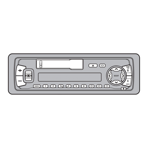
KEH-P4950J 3 7 63 1515 0 8.1 OPERATIONS PAUSE/BSM button BAND button 5/∞/2/3 EJECT button EQ button buttons Cassette door Detach button Buttons 1–6 SOURCE/OFF button DISPLAY button CLOCK button L 13942296513 RPT button AUDIO button +/– button u163... -
Page 46: Manual
KEH-P4950J 3 7 63 1515 0 L 13942296513 u163 http://www.xiaoyu163.com... -
Page 47: Manual
KEH-P4950J 3 7 63 1515 0 L 13942296513 u163 http://www.xiaoyu163.com... -
Page 48: Manual
KEH-P4950J 3 7 63 1515 0 8.2 SPECIFICATIONS General FM tuner Power source ..14.4 V DC (10.8 – 15.1 V allowable) Frequency range ........87.5 – 108 MHz Grounding system ........Negative type Usable sensitivity ............ 11 dBf (1.0 µV/75 Ω, mono, S/N: 30 dB)
Need help?
Do you have a question about the KEH-P4950J and is the answer not in the manual?
Questions and answers