Advertisement
Quick Links
SERVICE MANUAL
COMPACT DISC STEREO
CASSETTE RECEIVER
SYSTEM
NSX-AJ14<U>
NSX-BL14<HS,EZ,K>
NSX-BL16<EZ>
NSX-BL14E<HA>
• This Service Manual is the "Revision Publishing" and replaces "Simple
Manual" NSX-AJ14(U)/BL14E(HA)/BL14(HS,EZ,K)/BL16(EZ),
(S/M Code No. 09-003-428-8T2).
• If requiring information about the CD mechanism, see Service Manual
of AZG-1 (S/M Code No. 09-001-335-3NC).
NSX-AJ14
NSX-BL14E
NSX-BL14
NSX-BL16
BASIC TAPE MECHANISM : ZZM-2 PR1NM
BASIC CD MECHANISM : AZG-1 ZA3RNDM
CD
CASSEIVER
CX-NAJ14
CX-NBL14
CX-NBL14E
S/M Code No. 09-004-428-8R2
REMOTE
SPEAKER
CONTROLLER
SX-NAJ11
SX-NBL11
RC-ZAS02
SX-NBL16
SX-NBL17
U
HA
HS, EZ, K
EZ
Advertisement

Subscribe to Our Youtube Channel
Related Manuals for Aiwa NSX-BL14E


Summary of Contents for Aiwa NSX-BL14E
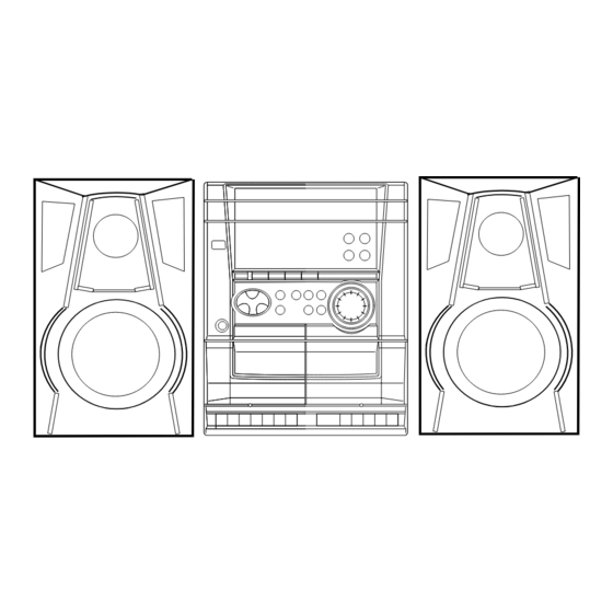
- Page 1 NSX-AJ14 NSX-BL14E NSX-BL14 HS, EZ, K NSX-BL16 SERVICE MANUAL COMPACT DISC STEREO BASIC TAPE MECHANISM : ZZM-2 PR1NM CASSETTE RECEIVER BASIC CD MECHANISM : AZG-1 ZA3RNDM REMOTE SYSTEM SPEAKER CASSEIVER CONTROLLER NSX-AJ14<U> CX-NAJ14 SX-NAJ11 NSX-BL14<HS,EZ,K> SX-NBL11 CX-NBL14 RC-ZAS02 NSX-BL16<EZ> SX-NBL16 NSX-BL14E<HA>...
-
Page 2: Specifications
SPECIFICATIONS <FM tuner section> Tuning range 87.5 MHz to 108 MHz <Speaker system>SX-NBL17<HA>,SX-NBL11<HS,14EZ,K>, Usable sensitivity (IHF) U,HA,HS: 13.2 dBf SX-NBL16<16EZ> EZ,K: 16.8 dBf Speaker System 2 way, bass reflex (magnetic shielded Antenna terminals 75 ohms (unbalanced) type) Speaker units Woofer: <AM/MW tuner section>... -
Page 3: Protection Of Eyes From Laser Beam During Servicing
PROTECTION OF EYES FROM LASER BEAM DURING SERVICING CAUTION This set employs laser. Therefore, be sure to follow carefully Use of controls or adjustments or performance of proce- the instructions below when servicing. dures other than those specified herein may result in hazardous radiation exposure. -
Page 4: Note On Before Starting Repair
NOTE ON BEFORE STARTING REPAIR 1. Forced discharge of electrolytic capacitor of power supply block When repair is going to be attempted in the set that uses relay circuit in the power supply block, electric potential is kept charged across the electrolytic capacitors (C101, 102) even though AC power cord is removed. - Page 5 In such a case, check also if the POWER AMPLIFIER circuit or power supply circuit has any abnormalities or not. 2-2. Regarding reset There are cases that the machine does not work correctly because the MICROCOMPUTER is not reset even though the AC power cord is re-inserted, or the software reset (pressing the STOP key + POWER key) is performed.
-
Page 6: Electrical Main Parts List
ELECTRICAL MAIN PARTS LIST REF. NO. PART NO. KANRI DESCRIPTION REF. NO. PART NO. KANRI DESCRIPTION 87-016-495-000 CAP,E 3300-25 M SMG<HA,U> 87-A10-520-000 CAP,E 3300-35 M SMG<EZ,K,HS> 8A-NFA-616-010 C-IC,M38B59MFH-E251FP<16EZ> 87-016-495-000 CAP,E 3300-25 M SMG<HA> 8A-NFA-615-010 C-IC,M38B57MCH-E236FP<EXCEPT 16EZ> 87-016-051-000 CAP,E 2200-35 SMG<EZ,K,HS> 87-A21-397-010 IC,STK490-070<HA>... - Page 7 REF. NO. PART NO. KANRI DESCRIPTION REF. NO. PART NO. KANRI DESCRIPTION C183 87-010-387-080 CAP,E 470-25 SME<U,EZ,K> C670 87-010-322-080 C-CAP,S 100P-50 CH<EZ,K,HA> C184 87-010-403-080 CAP, ELECT 3.3-50V<U,EZ,K> C677 87-010-197-080 CAP, CHIP 0.01 DM C185 87-018-209-080 CAP, TC U 0.1-50ZF<EZ,K> C771 87-010-263-080 CAP, ELECT 100-10V C200...
- Page 8 REF. NO. PART NO. KANRI DESCRIPTION REF. NO. PART NO. KANRI DESCRIPTION C952 87-010-197-080 CAP, CHIP S 0.01-25 KB<EZ,K> FRONT C.B C957 87-010-311-080 CAP, CHIP S 12P-50 JCH<EZ,K> C958 87-010-197-080 CAP, CHIP S 0.01-25 KB<EZ,K> C101 87-010-196-080 CHIP CAPACITOR,0.1-25 C959 87-010-196-080 CHIP CAPACITOR,0.1-25 C102...
- Page 9 REF. NO. PART NO. KANRI DESCRIPTION S329 87-A90-164-080 SW,TACT SKQAB(N) S330 87-A90-164-080 SW,TACT SKQAB(N) S331 87-A90-164-080 SW,TACT SKQAB(N) SFR701 87-024-431-080 SFR,3.3K RH063EC VR401 87-NB7-602-010 VR,RTRY 10KAX1 1V<HS> PT C.B 87-010-387-080 CAP,E 470-25 SME<HA,HS> 87-010-403-080 CAP, ELECT 3.3-50V<HA,HS> C183 87-010-387-080 CAP, ELECT 470-25 M<U,EZ,K> C184 87-010-403-080 CAP, ELECT 3.3-50V<U,EZ,K>...
-
Page 10: Transistor Illustration
TRANSISTOR ILLUSTRATION S D G E C B E C B B C E 2SB1342 2SJ460 CSA952 DTC114ES 2SB1370 2SK2541 CSC4115 2SD1933 KTA1266 KTC3198 KTC3199 E B C B C E E C B 2SC3331 2SA1981 CC5551 2SK360 2SA1235 CMBT5551 2SC2714 KRA102 KRA107... - Page 11 FL (10-BT-224GNK) GRID ASSIGNMENT AND ANODE CONNECTION GRID ASSIGNMENT – –...
- Page 12 ANODE CONNECTION – –...
- Page 13 WIRING - 1 (MAIN: U) - 13 -...
- Page 14 SCHEMATIC DIAGRAM _ 1 (MAIN 1 / 2 : AMP SECTION) <U> – 14 –...
- Page 15 SCHEMATIC DIAGRAM _ 2 (MAIN 2 / 2 : TUNER SECTION) <U> – 15 –...
- Page 16 WIRING - 2 (MAIN: HA) - 16 -...
- Page 17 SCHEMATIC DIAGRAM _ 3 (MAIN 1 / 2 : AMP SECTION) <HA> – 17 –...
- Page 18 SCHEMATIC DIAGRAM _ 4 (TUNER SECTION : HA) – 18 –...
- Page 19 WIRING - 3 (MAIN: HS) - 19 -...
- Page 20 SCHEMATIC DIAGRAM _ 5 (MAIN 1 / 2 : AMP SECTION) <HS> – 20 –...
- Page 21 SCHEMATIC DIAGRAM _ 6 (MAIN 2 / 2 : TUNER SECTION) <HS> – 21 –...
- Page 22 WIRING - 4 (MAIN: EZ, K) - 22 -...
- Page 23 SCHEMATIC DIAGRAM _ 7 (MAIN 1 / 2 : AMP SECTION)<EZ, K> – 23 –...
- Page 24 SCHEMATIC DIAGRAM _ 8 (TUNER SECTION : EZ, K) – 24 –...
- Page 25 WIRING - 5 (FRONT: HS, HA, U) - 25 -...
- Page 26 SCHEMATIC DIAGRAM _ 9 (FRONT : HS, HA, U) – 26 –...
- Page 27 WIRING - 6 (FRONT: EZ, K) - 27 -...
- Page 28 SCHEMATIC DIAGRAM _ 10 (FRONT : EZ, K) – 28 –...
- Page 29 WIRING - 7 (PT: EZ, K, U) - 29 -...
- Page 30 SCHEMATIC DIAGRAM _ 11 (PT : EZ, K, U) – 30 –...
- Page 31 WIRING - 8 (PT: HA) - 31 -...
- Page 32 SCHEMATIC DIAGRAM _ 12 (PT : HA) – 32 –...
- Page 33 WIRING - 9 (PT: HS) - 33 -...
- Page 34 SCHEMATIC DIAGRAM _ 13 (PT : HS) – 34 –...
- Page 35 WIRING - 10 (DECK)
- Page 36 IC BLOCK DIAGRAM IC,M62495AFP IC,LA1843 / IC,LA1844L-A IC,BU1920FS IC,LC72131D – 36 –...
- Page 37 IC DESCRIPTION IC, M38B57MCH-E236FP / M38B59MFH-E251FP Description Pin No. Pin Name I-SIG RDS signal level A/D input. (Not used) I-HOLD Hold voltage level A/D input. I-SW (CD) CD mecha SW A/D input. I-DISH CD turn-table position check A/D input. I-KEY2 KEY2 A/D input.
- Page 38 Pin No. Pin Name Description O-DISH_R CD turn-table reverse turn output. O-DISH_F CD turn-table forward turn output. I-SUBQ Sub code-Q data input. O-CD_CE CD DSP chip enable output. I-WRQ CD WRQ input. O-CLK (CD) CD control clock output . O-DATA (CD) CD control data output.
- Page 39 ADJUSTMENT <TUNER / DECK> A MAIN C.B L801 L802 TC942 L941 TP4 (DC) IC801 L942 TP3 (DC) IC301 L951(1/3) (CLK) TP8 (LCH) TP1(VT) TP9 (RCH) FFE831 DECK–1 R/P/E, DECK-2 P HEAD B FRONT C.B FL201 TP5 (K-SCAN) IC101 L101 SFR701 –...
- Page 40 < TUNER SECTION > < DECK SECTION > 1. Clock frequency Check 10. Tape Speed Adjustment (DECK 1) Settings : • Test point : TP2 (CLK) Settings : • Test tape : TTA–100 Method : Set to AM 1710kHz(U, HA), MW 1602kHz(HS,EZ,K) •...
- Page 41 MECHANICAL EXPLODED VIEW 1 / 1 AZG-1 ZA3RNDM 31 30 FL201 P.C.B P.C.B HT-SINK HA ONLY PLATE,EARTH ZZM-2 PR1NM 14K,16EZ HLDR1 (EZ,K ONLY) 14U,14EZ HLDR2 ONLY P.C.B WIRE,BINDER P.C.B HS ONLY P.C.B HT-SINK, FIN-S CHAS, MAIN P.C.B P.C.B (14U ONLY) (HA ONLY) P.C.B –...
-
Page 42: Mechanical Parts List
18 8A-NFZ-008-010 KEY,POWER<EXCEPT 14U> 43 8A-NFA-215-010 PLATE,PL HR<14HS> 18 8A-NFZ-071-010 KEY,POWER AJ14<14U> 44 8A-NFB-202-010 HLDR,HT-SINK S STEEL<14U> 19 87-CE3-023-010 BADGE,AIWA 30N SILV 45 85-NF5-628-010 F-CABLE 7P-2.5<14K,14EZ,16EZ,14U> 20 8A-NFZ-002-010 PANEL,TRAY H<EXCEPT 14U> A 87-067-703-010 TAPPING SCREW, BVT2+3-10 20 8A-NFZ-044-010 PANEL,TRAY U AJ14<14U>... - Page 43 TAPE MECHANISM EXPLODED VIEW 1 / 1 TERMINAL,LB1 TERMINAL,LB1 – 43 –...
-
Page 44: Tape Mechanism Parts List
TAPE MECHANISM PARTS LIST 1 / 1 REF. NO. PART NO. KANRI DESCRIPTION REF. NO. PART NO. KANRI DESCRIPTION 1 8Z-ZM1-254-210 SPR-C,REEL R 36 8Z-ZM1-220-110 LEVER,REC SENSOR 2 8Z-ZM1-225-110 GEAR,REEL R 37 8Z-ZM1-249-010 SPR-T,FR 3 8Z-ZM1-253-110 SPR-C,AUTO SENSOR 38 8Z-ZM1-242-110 SPR-T,FF/REW 4 8Z-ZM1-217-110 LEVER,AUTO SENSOR... - Page 45 SPEAKER DISASSEMBLY INSTRUCTIONS Type.1 Type.4 Insert a flat-bladed screwdriver into the position indicated by the TOOLS arrows and remove the panel. Remove the screws of each speaker 1 Plastic head hammer unit and then remove the speaker units. 2 (() flat head screwdriver 3 Cut chisel How to Remove the PANEL, FR Type.2...
-
Page 46: Accessories / Package List
SPEAKER PARTS LIST SX-NBL11(Y1SL,YSC9,YSC,YSL) / SX-NBL16(YSC9,YSC) SX-NBL17(YLSC9,YLSC) / SX-NAJ11(YUSL) REF. NO. PART NO. KANRI DESCRIPTION 1 8A-NSB-001-010 PANEL,FR 2 8A-NSB-014-010 GRILLE,FRAME ASSY R<16YSC> 2 8A-NSB-003-010 GRILLE,FRAME ASSY<EXCEPT 16YSC> 3 8Z-NSL-601-110 SPKR, W120<YSC9> 3 8Z-NSL-603-010 SPKR, W 120<YSC9> 3 8A-NSL-602-010 SPKR, 120<YLSC9,YLSC> 3 8A-NSL-606-010 SPKR, W120<11YSC,16YSC,YSL,YUSL,Y1SL>... - Page 47 2–11, IKENOHATA 1–CHOME, TAITO-KU, TOKYO 110, JAPAN TEL:03 (3827) 3111 9630472 0251431 Printed in Singapore...
Need help?
Do you have a question about the NSX-BL14E and is the answer not in the manual?
Questions and answers