Table of Contents
Advertisement
Quick Links
USER MANUAL
QUICK INSTALLATION GUIDE
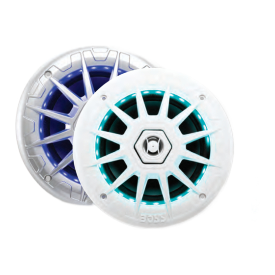
MRGB65 / MRGB65S
MARINE GRADE RGB 6.5" COAX SPEAKERS
BOSS Audio Systems
3451 Lunar Court • Oxnard, CA 93030
www.bossaudio.com | 800.999.1236
Tech Support: www.bossaudio.com/support
0215
VER:1.0 EN
PRINTED IN CHINA
USER MANUAL
QUICK INSTALLATION GUIDE
MRGB65 / MRGB65S
MARINE GRADE
6.5" COAX SPEAKERS
FEATURING 17 COLOR RGB LED's
and RF REMOTE CONTROLLER
Advertisement
Table of Contents

Related Manuals for Boss MRGB65


Summary of Contents for Boss MRGB65
-
Page 1: User Manual
USER MANUAL USER MANUAL QUICK INSTALLATION GUIDE QUICK INSTALLATION GUIDE MRGB65 / MRGB65S MRGB65 / MRGB65S MARINE GRADE RGB 6.5” COAX SPEAKERS MARINE GRADE 6.5″ COAX SPEAKERS BOSS Audio Systems 3451 Lunar Court • Oxnard, CA 93030 www.bossaudio.com | 800.999.1236 Tech Support: www.bossaudio.com/support... -
Page 2: Table Of Contents
TABLE OF CONTENTS BEFORE YOU START ------------------------------------------------------------------ 2 IMPORTANT SAFETY PRECAUTIONS INSTALLATION PRECAUTIONS WIRE DIAGRAM-------------------------------------------------------------------------- 3 BEFORE INSTALLING THIS PRODUCT ------------------------------------------ 4 TECHNICAL SUPPORT SUGGESTED MOUNTING LOCATIONS ------------------------------------------ 5 GETTING STARTED -------------------------------------------------------------------- 6 SPEAKER TEMPLATE ----------------------------------------------------------------- 7 TROUBLE SHOOTING GUIDE ------------------------------------------------------- 8 SPECIFICATIONS ------------------------------------------------------------------------ 8 TECHNICAL SUPPORT All rights reserved. -
Page 3: Before You Start
2x- Speaker Wire & Mounting Hardware Kit other hazards ■ Refer any repairs to a qualified BOSS AUDIO SYSTEMS Service Center ■ The MRGB65 LED RGB SYNC HUB should be wired directly to a normally 1x- User Manual / 1x- Warranty Card USER MANUAL open switch or relay. -
Page 4: Wire Diagram
Ensure that the ground cable is properly connected to metal parts of the TO CONNECT MORE THAN ONE SET OF MRGB65 TOGETHER, vehicles body frame or direct to the battery if your vehicle does not have a PLUG THE SYNC OUT TO THE SYNC... -
Page 5: Suggested Mounting Locations
SUGGESTED MOUNTING LOCATIONS GETTING STARTED The MRGB65 can mounted in three different configurations: GETTING TO KNOW YOUR MRGB65 RF CONTROLLER Always double check for mountig depth limitations, never cut before you check 1) RF controller range: Up to 25ft (LoS) -
Page 6: Speaker Template
SPEAKER TEMPLATE TROUBLE SHOOTING GUIDE TROUBLE CAUSE SOLUTION TEMPLATE FOR REEFERENCE ONLY - NOT TO SCALE The fuse is blown Check / replace the fuse RGB Unit will not turn on Switch not engaged Turn to on position Blown speaker Replace faulty speaker Volume is low / muted Press the volume level up...
Need help?
Do you have a question about the MRGB65 and is the answer not in the manual?
Questions and answers