Table of Contents
Advertisement
In the interests of user-safety (Required by safety regulations in some countries) the set should be re-
stored to its original condition and only parts identical to those specified should be used.
» IMPORTANT SERVICE SAFETY PRECAUTION ........................................................................................ 2
» SPECIFICATIONS ........................................................................................................................................ 5
» OPERATION MANUAL ................................................................................................................................. 6
» DIMENSIONS ............................................................................................................................................... 8
» REMOVING OF MAJOR PARTS ..................................................................................................................9
» ADJUSTING PROCEDURE OF EACH SECTION .....................................................................................13
» PUBLIC MODE SETTING PROCEDURE ..................................................................................................32
» TROUBLE SHOOTING TABLE ..................................................................................................................38
» CHASSIS LAYOUT .....................................................................................................................................43
» BLOCK DIAGRAM ......................................................................................................................................44
» OVERALL WIRING DIAGRAM ...................................................................................................................46
» DESCRIPTION OF SCHEMATIC DIAGRAM ............................................................................................. 48
» SCHEMATIC DIAGRAM ............................................................................................................................. 49
» PRINTED WIRING BOARD ASSEMBLIES ................................................................................................71
» REPLACEMENT PARTS LIST ....................................................................................................................81
» PACKING OF THE SET ..............................................................................................................................93
SHARP CORPORATION
SERVICE MANUAL
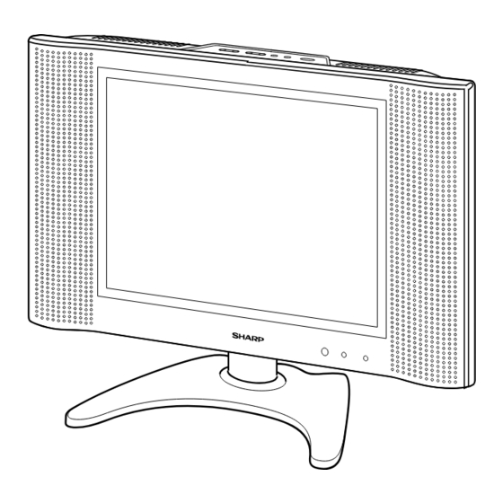
LCD COLOR TELEVISION
LC-13B4U-S
LC-13B4U-B
MODELS
CONTENTS
This document has been published to be used for
after sales service only.
The contents are subject to change without notice.
LC-13B4U-S
LC-13B4U-B
S63E4LC-13B4U
Page
Advertisement
Table of Contents

Related Manuals for Sharp LC-13B4U-S


Summary of Contents for Sharp LC-13B4U-S
-
Page 1: Table Of Contents
LC-13B4U-S LC-13B4U-B SERVICE MANUAL S63E4LC-13B4U LCD COLOR TELEVISION LC-13B4U-S LC-13B4U-B MODELS In the interests of user-safety (Required by safety regulations in some countries) the set should be re- stored to its original condition and only parts identical to those specified should be used. -
Page 2: Important Service Safety Precaution
LC-13B4U-S LC-13B4U-B IMPORTANT SERVICE SAFETY PRECAUTION Ë Service work should be performed only by qualified service technicians who are thor- oughly familiar with all safety checks and the servicing guidelines which follow: ground, such as electrical conduit or electrical ground WARNING connected to an earth ground. - Page 3 LC-13B4U-S LC-13B4U-B PRECAUTIONS A PRENDRE LORS DE LA REPARATION Ë Ne peut effectuer la réparation qu' un technicien spécialisé qui s'est parfaitement accoutumé à toute vérification de sécurité et aux conseils suivants. conduite électrique ou une prise de terre branchée à...
- Page 4 LC-13B4U-S LC-13B4U-B Precautions for using lead-free solder 1 Employing lead-free solder "All PWBs" of this model employs lead-free solder. The LF symbol indicates lead-free solder, and is attached on the PWBs and service manuals. The alphabetical character following LF shows the type of lead-free solder.
-
Page 5: Specifications
AC cord, Cable clamp (x2), Operation manual As a part of policy of continuous improvement, SHARP reserves the right to make design and specification changes for product improvement without prior notice. The performance specification figures indicated are nominal values of... -
Page 6: Operation Manual
LC-13B4U-S LC-13B4U-B OPERATION MANUAL... - Page 7 LC-13B4U-S LC-13B4U-B...
-
Page 8: Dimensions
LC-13B4U-S LC-13B4U-B DIMENSIONS Unit: inch (mm) MENU TV/VIDEO MAIN POWER (292.6) (429) (267) (61.5) (100) VIDEO AV-IN1 AUDIO S-VIDEO VIDEO AV-IN 2/OUT AUDIO HEAD PHONE COMPONENT ANT. USE THE SUPPLIED AC ADAPTER. (PART NO. LOCATED ON THE MODEL LABEL.) POWER... -
Page 9: Removing Of Major Parts
LC-13B4U-S LC-13B4U-B REMOVING OF MAJOR PARTS 1. Remove the stand fixing screws (4 pcs.). 2. Remove the two terminal covers. 3. Remove the terminal section fixing screws (2 pcs.). 4. Remove the cabinet B fixing screws (8 pcs.). 5. Cabinet A is opend order of , and detach the Cabinet B. - Page 10 LC-13B4U-S LC-13B4U-B 9. Remove the inverter PWB fixing screws (2 pcs.). 10. Remove the main PWB fixing screws (3 pcs.). 11. Detach the chassis frame cover. 12. Remove the tuner PWB fixing screws (3 pcs.) . 13. Remove the R/C, LED PWB fixing screws (2 pcs.).
- Page 11 LC-13B4U-S LC-13B4U-B » Precautions in handling the LCD panels 1. Work in a clean room (with humidities below 50%). 2. Be sure to wear an anti-static armband. 3. Handle the panels on an electroconductive mat. 4. Be careful not to fall, shake and shock the panels.
- Page 12 LC-13B4U-S LC-13B4U-B Precautions at the time of the side B(back) service of digital unit. 1. Remove only SC2002 of the FFC for connection between Main unit (SC2002) and Tuner unit(SC3403), and connect the extended cable (QCNW-A556WJZZ) for service. 2. Remove the FFC for connection between Main unit (SC1204) and LCD panel unit, and connect the extended cable (QCNW-A553WJZZ) for service.
-
Page 13: Adjusting Procedure Of Each Section
LC-13B4U-S LC-13B4U-B ADJUSTING PROCEDURE OF EACH SECTION The best adjustment is made before shipping. If any position deviation is found or after part replace is performed, adjust as follows. 1. Preparation for Adjustments Use the exclusive-use AC adapter or stable DC power supply. - Page 14 LC-13B4U-S LC-13B4U-B 4. Adjustments Adjustment Adjusting conditions Adjusting method 1. Adjust the "B+ Adj" value to 1. Connect the DC voltmeter to B+ Adjustment pin (4) of P3701. 5.0±0.02V with R3714. Make exact (R3714) adjustment of the 5.00V level be- cause it will be the reference for all the other supply voltages.
- Page 15 LC-13B4U-S LC-13B4U-B Adjustment Adjusting conditions Adjusting method White balance adjustment 1. Receive the monoscope pattern RCUTOFF Red cut-off adjustment signal. GCUTOFF Green cut-off adjustment BCUTOFF 2. Select Page 3 of Adjustment Process Blue cut-off adjustment R-GAIN White balance mode. G-GAIN...
- Page 16 LC-13B4U-S LC-13B4U-B Adjustment Adjusting conditions Adjusting method 1. Call up the adjustment process menu If the wrong data has been sent: PROM data write and get Page 6 displayed on-screen. 1. Initialize the E PROM. (Take the 2. Enter "A40000002681" for the "I special mode setting procedure (1).)
- Page 17 LC-13B4U-S LC-13B4U-B Test patterns in adjustment process mode [1] IC801 (Video decoder) test patterns 1-1. Getting the test patterns displayed Put the screen in AV1, AV2 or COMPONENT but keep out any signal. Call the adjustment process mode, select "TEST PATTERN" in the 3rd line of VPC 1, make the settings 1 thru 6, and the following test patterns show up.
- Page 18 LC-13B4U-S LC-13B4U-B Pin functions of microprocessor IC (IC2001) RH-iXA620WJZZQ In Power Saving* Pin No. Name of Terminal Name of Function Function in Normal Times Within 1 min. after Power-OFF by R/C Unit VHOLD1 Vhold For CLOSED CAPTION HLF1 For CLOSED CAPTION P94/DA1/SCL3/RXD2 N.C.
- Page 19 LC-13B4U-S LC-13B4U-B In Power Saving* Pin No. Name of Terminal Name of Function Function in Normal Times Within 1 min. after Power-OFF by R/C Unit P43/A19 Adjusting process P42/A18 LED_POW Green by TV power supply LED control at “H”, and red at “L”...
- Page 20 LC-13B4U-S LC-13B4U-B Table of Adjusting Process Defaults 1000 order 100 and 10 orders Item Initial Values Min. Value Max. Value Display Content Title No. Page No. ← MODEL A620 Selection of model name (For prevention of malfunction, it is impossible to change it.) →...
- Page 21 LC-13B4U-S LC-13B4U-B 1000 order 100 and 10 orders Item Initial Values Min. Value Max. Value Display Content Title No. Page No. Equalizer setting 1 (External input) SOUND3 EXT GEQ BAND1 +0.5 -12.0 +12.0 Unit 0.5 Equalizer setting 2 (External input) EXT GEQ BAND2 +1.0...
- Page 22 LC-13B4U-S LC-13B4U-B 1000 order 100 and 10 orders Item Initial Values Min. Value Max. Value Display Content Title No. Page No. VPC5 PAL-M AVO START 1023 Decimal Horizontal position setting PAL-M SFIF 4095 Decimal Horizontal position setting PAL-M SCINC1 1635...
- Page 23 LC-13B4U-S LC-13B4U-B 1000 order 100 and 10 orders Item Initial Values Min. Value Max. Value Display Content Title No. Page No. VPC13 PAL60 AVO START 1023 Decimal Horizontal position setting PAL60 SFIF 4095 Decimal Horizontal position setting PAL60 SCINC1 1635...
- Page 24 LC-13B4U-S LC-13B4U-B 1000 order 100 and 10 orders Item Initial Values Min. Value Max. Value Display Content Title No. Page No. DPS2 N358 TV PKLEVEL Decimal DPS h'7B[7:4] = h'7B[3:0] N358 AV PKLEVEL Decimal DPS h'7B[7:4] = h'7B[3:0] N358 TV PKCORRED7A...
- Page 25 LC-13B4U-S LC-13B4U-B 1000 order 100 and 10 orders Item Initial Values Min. Value Max. Value Display Content Title No. Page No. DPS8 PAL-M TV LTI Decimal DPS h’77[7:0] PAL-M AV LTI Decimal DPS h’77[7:0] PAL-M TV LMODE79 Decimal DPS h’79[7:0]...
- Page 26 LC-13B4U-S LC-13B4U-B 1000 order 100 and 10 orders Item Initial Values Min. Value Max. Value Display Content Title No. Page No. DPS14 PAL-N TV BLEMODE Decimal DPS h’74[7:6] PAL-N AV BLEMODE Decimal DPS h’74[7:6] PAL-N TV BGAINREF71 Decimal DPS h’71[7:0]...
- Page 27 LC-13B4U-S LC-13B4U-B 1000 order 100 and 10 orders Item Initial Values Min. Value Max. Value Display Content Title No. Page No. DPS22 SECAM AV PKLEVEL Decimal DPS h’7B[7:4] = h’7B[3:0] SECAM AV PKCORRED7A Decimal DPS h’7A[7:0] SECAM AV PKCFSOFT7C Decimal DPS h’7C[2:0]...
- Page 28 LC-13B4U-S LC-13B4U-B 1000 order 100 and 10 orders Item Initial Values Min. Value Max. Value Display Content Title No. Page No. DPS31 N443 AV COLOR Decimal Changes to DPS control (h’88[5:0]) N443 AV TINT +/- decimal Changes to DPS control (h’89[5:0])
- Page 29 LC-13B4U-S LC-13B4U-B 1000 order 100 and 10 orders Item Initial Values Min. Value Max. Value Display Content Title No. Page No. DPS40 D2 HPRESC FIL42 Decimal DPS h'42[5:0] D2 HSCPRESC 4095 Decimal DPS h'40[7:0],h'41[3:0] D2 HPOSC UPSF60 Decimal DPS h'60[7:6]...
- Page 30 LC-13B4U-S LC-13B4U-B 1000 order 100 and 10 orders Item Initial Values Min. Value Max. Value Display Content Title No. Page No. DPS45 DPS NLC A6 FF Hexadecimal No title No. DPS NLC A8 FF Hexadecimal (Because DPS NLC AA FF Hexadecimal...
- Page 31 LC-13B4U-S LC-13B4U-B 1000 order 100 and 10 orders Item Initial Values Min. Value Max. Value Display Content Title No. Page No. OTHERS1 L_ERROR WAIT 30 Decimal + “s” Every 1S (Time taken until error port checking is started) L _ERROR H TIME 1.0s...
-
Page 32: Public Mode Setting Procedure
LC-13B4U-S LC-13B4U-B PUBLIC MODE SETTING PROCEDURE 1. How to start Public Mode ∫ There are three ways to display the hotel mode setting screen as mentioned below. 1 1) Press the MENU and Sound Vol + keys of the unit and turn ON the power. - Page 33 LC-13B4U-S LC-13B4U-B 2. How to exit Public Mode There are several ways to exit the hotel mode setting screen as mentioned below. ∫ Turn OFF the power by power input key. ( ) ∫ Select "ENTER". ( ) ∫ Move the cursor to "RESET" and press the "FLASHBACK" key. (Mode changes to normal mode.) ( ) ...
- Page 34 LC-13B4U-S LC-13B4U-B 5. On Setting Items (1) MAXIMUM VOLUME Option Adjustable within the range of 1 to 60 (Not looped) Default Function Even when the sound volume is adjusted to higher level, adjusted value does not increase any more. (Unit speaker and headphone) ∫...
- Page 35 LC-13B4U-S LC-13B4U-B (5) ON SCREEN DISPLAY Option "YES" or "NO" selection (Looped) Default "YES" Function When "NO" is set, OSD display is made invalid. ∫ Messages for V-CHIP BLOCK and CLOSED CAPTION are displayed irrespective of setting. Exception ∫ Checking process, Setting at the time of shipment (including F7-SETUP), adjusting process and hotel mode setting screens should be able to display.
- Page 36 LC-13B4U-S LC-13B4U-B Specifications of Sound Only Mode Function is should be added during operation of remote control BRIGHT button. " " BRIGHTNESS [Bright] ⇒ BRIGHTNESS [Normal] ⇒ BRIGHTNESS [Dark] ⇒ BRIGHTNESS [OFF] ⇒ BRIGHTNESS [Bright] 2 When mode is selected, the screen is muted, the following message appears and time is counted.
- Page 37 LC-13B4U-S LC-13B4U-B Table of Key Allocation in Sound Only Mode (Unit keys/Remote control keys) Name of Key Allocation Unit keys POWER Reset TV/VIDEO Temporary recovery MENU Reset Temporary recovery Temporary recovery Remote control POWER In Normal = Reset In Power-ON fixed = Temporary recovery PIC.
-
Page 38: Trouble Shooting Table
LC-13B4U-S LC-13B4U-B TROUBLE SHOOTING TABLE... - Page 39 LC-13B4U-S LC-13B4U-B TROUBLE SHOOTING TABLE (Continued)
- Page 40 LC-13B4U-S LC-13B4U-B TROUBLE SHOOTING TABLE (Continued)
- Page 41 LC-13B4U-S LC-13B4U-B TROUBLE SHOOTING TABLE (Continued)
- Page 42 LC-13B4U-S LC-13B4U-B TROUBLE SHOOTING TABLE (Continued)
-
Page 43: Chassis Layout
LC-13B4U-S LC-13B4U-B CHASSIS LAYOUT OPERATION Unit INVERTER Unit MAIN Unit TUNER Unit R/C, LED Unit... -
Page 44: Block Diagram
LC-13B4U-S LC-13B4U-B BLOCK DIAGRAM SC3403 AGC,AFT,SAW_SW,MODE 1,MODE 2 TV_V VPC_Y VPC_PB,VPC_PR TUNER TU3201 SIF AMP Q3201,Q3202 V1_V INPUT AV1_L,R VIDEO SWITCH V_IN S-VIDEO INPUT IC3401 IC3502 V2_V IN/OUT AV2_L,R IN/OUT V_IN/OUT INPUT/OUTPUT AUDIO IN/OUT VIDEO IN/OUT SWITCH SWITCH IC3501,Q3501 Q3502-Q3505... - Page 45 LC-13B4U-S LC-13B4U-B SC2002 VIDEO CONTROLLER PANEL DECODER R0 7,G0 7,B0 7 (DPS) (VPC) IC1201 FL802 IC806 V0,V7,V21 Q806 V64,V112 V176,V235 GRADATION V2V0 V255 FL801 POWER SYNC SEP VCOM Q803 IC1101 IC802 CSCOM CSYNC OSD R/G/B VLS,VGL,VEE VPC_Y SYNC GSP1,VSH SELECT...
-
Page 46: Overall Wiring Diagram
LC-13B4U-S LC-13B4U-B OVERALL WIRING DIAGRAM... - Page 47 LC-13B4U-S LC-13B4U-B...
-
Page 48: Description Of Schematic Diagram
LC-13B4U-S LC-13B4U-B DESCRIPTION OF SCHEMATIC DIAGRAM VOLTAGE MEASUREMENT CONDITION: 1. The voltages at test points are measured on exclusive AC adaptor and the stable supply voltage of AC 120V. Signals are fed by a color bar signal generator for servicing purpose and the above voltages are measured with a 20k ohm/V tester. -
Page 49: Schematic Diagram
LC-13B4U-S LC-13B4U-B SCHEMATIC DIAGRAM Ë R/C, LED and OPERATION Unit... - Page 50 LC-13B4U-S LC-13B4U-B Ë MAIN Unit-1/5...
- Page 51 LC-13B4U-S LC-13B4U-B...
- Page 52 LC-13B4U-S LC-13B4U-B Ë MAIN Unit-2/5...
- Page 53 LC-13B4U-S LC-13B4U-B...
- Page 54 LC-13B4U-S LC-13B4U-B Ë MAIN Unit-3/5...
- Page 55 LC-13B4U-S LC-13B4U-B...
- Page 56 LC-13B4U-S LC-13B4U-B Ë MAIN Unit-4/5...
- Page 57 LC-13B4U-S LC-13B4U-B...
- Page 58 LC-13B4U-S LC-13B4U-B Ë MAIN Unit-5/5...
- Page 59 LC-13B4U-S LC-13B4U-B...
- Page 60 LC-13B4U-S LC-13B4U-B Ë TUNER Unit-1/5...
- Page 61 LC-13B4U-S LC-13B4U-B...
- Page 62 LC-13B4U-S LC-13B4U-B Ë TUNER Unit-2/5...
- Page 63 LC-13B4U-S LC-13B4U-B...
- Page 64 LC-13B4U-S LC-13B4U-B Ë TUNER Unit-3/5...
- Page 65 LC-13B4U-S LC-13B4U-B...
- Page 66 LC-13B4U-S LC-13B4U-B Ë TUNER Unit-4/5...
- Page 67 LC-13B4U-S LC-13B4U-B...
- Page 68 LC-13B4U-S LC-13B4U-B Ë TUNER Unit-5/5...
- Page 69 LC-13B4U-S LC-13B4U-B...
-
Page 70: Inverter Unit
LC-13B4U-S LC-13B4U-B Ë INVERTER Unit... -
Page 71: Printed Wiring Board Assemblies
LC-13B4U-S LC-13B4U-B PRINTED WIRING BOARD ASSEMBLIES TUNER Unit (Side-A) - Page 72 LC-13B4U-S LC-13B4U-B TP3701 P3604 P3603 P3502 Q3601 FH3704 FH3703 FH3702 FH3701 R3754 Q3709 C3732 R3749 R3745 R3746 C3731 C3730 R3747 C3734 R3744 Q3707 R3737 R3734 C3729 Q3708 TU3201 R3732 L3701 C3722 R3204 C3024 R3206 D370 C3360 C3202 R3203 R3205 J3303...
- Page 73 LC-13B4U-S LC-13B4U-B P3301 P3602 P3302 P3601 R3351 R3601 R3352 R3350 D3604 R3603 R3602 P3701 C3610 C3608 R3605 R3606 Q3604 D3606 Q3605 R3515 R3610 R3754 D3607 R3761 Q3709 C3607 R3609 C3732 D3608 R3749 R3745 R3742 R3746 C3731 R3743 C3730 R3349 R3347...
- Page 74 LC-13B4U-S LC-13B4U-B MAIN Unit (Side-A)
- Page 75 LC-13B4U-S LC-13B4U-B TP2001 SC1204 C1227 C1228 C1229 C1230 C1231 C1232 C1233 R837 R841 R836 C851 C852 R1233 R1230 C1219 C831 R1229 C853 IC806 R847 C1214 C1211 R1224 C1204 C1205 C1206 C1207 C1208 R1217 FL802 C820 IC805 C1237 R1122 C818 C1235...
- Page 76 LC-13B4U-S LC-13B4U-B MAIN Unit (Side-B)
- Page 77 LC-13B4U-S LC-13B4U-B R1245 C1239 R1243 C1241 R812 R1248 R830 C810 R815 C821 R804 R817 Q804 C825 C823 R824 R1249 D1201 R808 R806 R826 C827 C828 D1202 D1204 D1203 R810 R1250 R1261 R1274 R1201 R1255 R1253 C1248 D1206 R1209 Q1210 R1275...
- Page 78 LC-13B4U-S LC-13B4U-B INVERTER Unit (Side-A)
- Page 79 LC-13B4U-S LC-13B4U-B R6511 FH6501 FH6500 R6509 R6507 C6511 C6503 R6502 C6502 R6500 R6501 Q6501 Q6500 T6501 T6500 INVERTER Unit (Chip Parts Side-A)
- Page 80 LC-13B4U-S LC-13B4U-B R/C, LED Unit (Side-A) D4022 R4023 Q4001 D4012 Q4007 R4024 RMC4002 D4014 D4011 R4029 R/C, LED Unit (Chip Parts Side-A) OPERATION Unit (Side-A) (QPWBSB770WJN2) S4701 OPERATION Unit (Chip Parts Side-A) (QPWBSB770WJN2)
-
Page 81: Replacement Parts List
4. DESCRIPTION in USA: Contact your nearest SHARP Parts Distributor to order. in CANADA: Contact SHARP Electronics of Canada Limited For location of SHARP Parts Distributor, Please call Toll- Phone (416) 890-2100 Free; 1-800-BE-SHARP MARK: SPARE PARTS-DELIVERY SECTION MARQUE: SECTION LIVRAISON DES PIECES DE RECHANGE Ref. - Page 82 LC-13B4U-S LC-13B4U-B Ref. No. Part No. Description Code Ref. No. Part No. Description Code DUNTKB767FE01 C715 RC-EZA132WJZZY J 10 Electrolytic C716 RC-KZA041WJZZY J 10 Ceramic MAIN UNIT (Continued) C718 RC-KZA041WJZZY J 10 Ceramic C719 RC-EZA123WJZZY J 100 6.3V Electrolytic C720 VCEASH0JN227MY J 220 6.3V Electrolytic...
- Page 83 LC-13B4U-S LC-13B4U-B Ref. No. Part No. Description Code Ref. No. Part No. Description Code DUNTKB767FE01 C2029 VCKYCY1HB561KY J 560p Ceramic RESISTORS MAIN UNIT (Continued) R701 VRS-CY1JF000JY 1/16W Metal Oxide R702 VRS-CY1JF682JY J 6.8k 1/16W Metal Oxide C1115 VCKYTV1CB334KY J 0.33...
- Page 84 LC-13B4U-S LC-13B4U-B Ref. No. Part No. Description Code Ref. No. Part No. Description Code DUNTKB767FE01 R2024 VRS-CY1JF103JY J 10k 1/16W Metal Oxide R2026 VRS-CY1JF223JY J 22k 1/16W Metal Oxide MAIN UNIT (Continued) R2029 VRS-CA1JF223JY J 22k 1/16W Metal Oxide R2032 VRS-CY1JF823JY...
- Page 85 LC-13B4U-S LC-13B4U-B Ref. No. Part No. Description Code Ref. No. Part No. Description Code DUNTKB767FE01 DUNTKB768DE01 MAIN UNIT (Continued) TUNER UNIT TUNER SC1204 QSOCN0206FJZZY J Socket, 30-pin(LG) SC2002 QSOCN0464FJZZY J Socket, 50-pin(MA) NOTE: THE PARTS HERE SHOWN ARE SUPPLIED AS AN...
- Page 86 LC-13B4U-S LC-13B4U-B Ref. No. Part No. Description Code Ref. No. Part No. Description Code DUNTKB768DE01 C3351 RC-KZ1025CEZZY Ceramic C3352 RC-EZA127WJZZY J 100 Electrolytic TUNER UNIT(Continued) C3354 VCCCCY1HH560JY J 56p Ceramic C3355 VCCCCY1HH560JY J 56p Ceramic PACKAGED CIRCUIT C3356 VCCCCY1HH560JY J 56p...
- Page 87 LC-13B4U-S LC-13B4U-B Ref. No. Part No. Description Code Ref. No. Part No. Description Code DUNTKB768DE01 R3342 VRS-CY1JF561JY J 560 1/16W Metal Oxide R3344 VRS-CY1JF104JY J 100k 1/16W Metal Oxide TUNER UNIT (Continued) R3345 VRS-CY1JF104JY J 100k 1/16W Metal Oxide R3347 VRS-CY1JF102JY...
- Page 88 LC-13B4U-S LC-13B4U-B Ref. No. Part No. Description Code Ref. No. Part No. Description Code DUNTKB768DE01 MISCELLANEOUS PARTS TUNER UNIT (Continued) FH3702 QFSHD1002CEZZ J Fuse Holder å FH3703 QFSHD1002CEZZ J Fuse Holder å R3561 VRS-CY1JF000JY 1/16W Metal Oxide FH3704 QFSHD1002CEZZ J Fuse Holder...
-
Page 89: Operation Unit
LC-13B4U-S LC-13B4U-B Ref. No. Part No. Description Code Ref. No. Part No. Description Code DUNTKB769DE01 DUNTKB771DE02 R/C, LED UNIT INVERTER UNIT TRANSISTORS TRANSISTORS Q4001 VSDTC144EE/-1Y J DTC144EE Q6500 VS2SC5886++-1Y J 2SC5886 Q4003 VSDTC144EE/-1Y J DTC144EE Q6501 VS2SC5886++-1Y J 2SC5886 Q4007 VSUMG4N++++-1Y J UMG4N... -
Page 90: Cabinet And Mechanical Parts
PSHEP0279CEZZ J Reflection Sheet-1 5-10 PSHEP0280CEZZ J Reflection Sheet-2 5-11 PSHEP0306CEZZ J Reflection Sheet(Cover), x2 AC CCABAA344WJ01 J Cabinet A Ass’y(LC-13B4U-S) BF 5-12 PSLDM4684CEFW J Back Shield CCABAA344WJ02 J Cabinet A Ass’y(LC-13B4U-B) BF 5-13 PSLDMA273WJZZ J Shield, x1 Not Available –... - Page 91 LC-13B4U-S LC-13B4U-B CABINET AND MECHANICAL PARTS MAIN PWB OPERATION PWB INVERTER PWB 1-13 1-11 TUNER PWB 1-13 1-12 5-12 5-14 5-10 1-10 R/C, LED PWB 5-13 5-11 5-15 5-17 5-16 5-18 3-13 3-2-1 3-2-2 3-10 3-12 3-12 3-11 3-11...
-
Page 92: Packing Parts
Code Ref. No. Part No. Description Code PACKING PARTS SUPPLIED ACCESSORIES (NOT REPLACEMENT ITEM) SPAKCA724WJZZ – Packing Case(LC-13B4U-S) — LHLDWA002WJSA J Cable Clamp, x2 SPAKCA726WJZZ – Packing Case(LC-13B4U-B) — (LC-13B4U-S) SPAKFA331WJZZ – Buffer Material(Accessories) — LHLDWA002WJSB J Cable Clamp, x2 SPAKPA211WJZZ –... -
Page 93: Packing Of The Set
LC-13B4U-S LC-13B4U-B PACKING OF THE SET Operation Manual (TiNS-A689WJZZ) Polyethylene Bag Cable Clamp (2pcs) (SSAKA0160CEZZ) (LHLDWA002WJSA:LC-13B4U-S) (LHLDWA002WJSB:LC-13B4U-B) Questionnaire card (TCADEA028WJZZ) Infrared R/C Unit "AAA" size Battery (2pcs) (RRMCGA152WJSA:LC-13B4U-S) (RRMCGA152WJSB:LC-13B4U-B) AC Cord (QACCD3097CEPA) Wrapping Paper Antenna Cable (SPAKPA211WJZZ) (QCNWG0003CEPA) AC Adapter... - Page 94 LC-13B4U-S LC-13B4U-B COPYRIGHT © 2003 BY SHARP CORPORATION ALL RIGHTS RESERVED. No part of this publication may be reproduced, stored in a retrieval system, or transmitted in any form or by any means, electronic, mechanical, photocopying, recording, or otherwise, without prior written permission of the publisher.
Need help?
Do you have a question about the LC-13B4U-S and is the answer not in the manual?
Questions and answers