Table of Contents
Advertisement
Quick Links
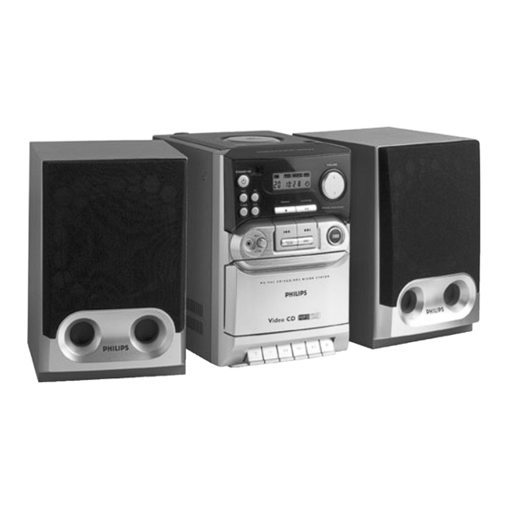
Micro System
Service Manual
TABLE OF CONTENTS
Handling chip components ............................................................1-1
Technical specification...................................................................2-1
Service tools ..................................................................................2-1
Service measurement setup ..........................................................2-2
Connections and controls ......................................................3-1...3-2
Disassembly diagram ....................................................................4-1
Pin description of ICs...........................................................4-2...4-10
Set block diagram ..........................................................................5-1
Set wiring diagram .........................................................................5-2
LED BOARD
circuit diagram ..........................................................................6-1
layout diagram ..........................................................................6-1
POWER BOARD
circuit diagram ..........................................................................7-1
layout diagram ..........................................................................7-1
circuit diagram ..........................................................................7-1
layout diagram ..........................................................................7-1
VCD & TAPE BOARD
circuit diagram - CD ..................................................................8-1
circuit diagram - TAPE..............................................................8-2
circuit diagram - MPEG.............................................................8-3
layout diagram - component side..............................................8-4
layout diagram - SMD side .......................................................8-5
©
Copyright 2001 Philips Consumer Electronics B.V. Eindhoven, The Netherlands
All rights reserved. No part of this publication may be reproduced, stored in a retrieval
system or transmitted, in any form or by any means, electronic, mechanical, photocopying,
or otherwise without the prior permission of Philips.
Published by SL 0232 Service Audio
Printed in The Netherlands
Subject to modification
VIDEO CD
circuit diagram ..........................................................................9-1
layout diagram ..........................................................................9-2
circuit diagram - power amplifier.............................................10-1
circuit diagram - tuner. ............................................................10-2
circuit diagram - karaoke. .......................................................10-3
layout diagram - component side............................................10-4
layout diagram - SMD side .....................................................10-5
ADJUSTMENT TABLE
tuner adjustment table ............................................................11-1
tape deck adjustment..............................................................11-1
Exploded view (main set).............................................................12-1
Mechanical partslist .....................................................................13-1
Electrical partslist...............................................................13-2...13-4
MC-V65
/21M/33
CLASS 1
LASER PRODUCT
© 3140 785 32160
Advertisement
Table of Contents

Related Manuals for Philips MC-V65


Summary of Contents for Philips MC-V65
-
Page 1: Table Of Contents
LASER PRODUCT © Copyright 2001 Philips Consumer Electronics B.V. Eindhoven, The Netherlands All rights reserved. No part of this publication may be reproduced, stored in a retrieval system or transmitted, in any form or by any means, electronic, mechanical, photocopying, or otherwise without the prior permission of Philips. -
Page 2: Handling Chip Components
1 - 1 HANDLING CHIP COMPONENTS HANDLING CHIP COMPONENTS © ñ WARNING WAARSCHUWING All ICs and many other semiconductors are susceptible to Alle IC´s en vele andere halfgeleiders zijn gevoelig voor electrostatic discharges (ESD). Careless handling during electrostatische ontladingen (ESD). repair can reduce life drastically. -
Page 3: Technical Specification
2 - 1 TECHNICAL SPECIFICATIONS GENERAL Grid -/21M 10kHz Mains voltage -/21M : 110 - 127 / 220 - 240V -/21M/33 : 9kHz -/33 230V ± 10% IF frequency 450 kHz ± 1 kHz Mains frequency : 50 / 60 Hz Switchable -/21M 18 dB S9 / 300kHz Sensitivity... -
Page 4: Service Measurement Setup
2 - 2 SERVICE MEASUREMENT Tuner FW Bandpass LF Voltmeter 250Hz-15kHz e.g. PM2534 e.g. 7122 707 48001 RF Generator e.g. PM5326 S/N and distortion meter e.g. Sound Technology ST1700B Use a bandpass filter to eliminate hum (50Hz, 100Hz) and disturbance from the pilottone (19kHz, 38kHz). Tuner AM (MW,LW) Bandpass LF Voltmeter... -
Page 5: Connections And Controls
3 - 1 CONNECTION AND CONTROLS... - Page 6 3 - 2 CONNECTION AND CONTROLS CS xx xxx...
- Page 7 3 - 3 CONNECTION AND CONTROLS...
-
Page 8: Disassembly Diagram
4 - 1 4 - 1 DISASSEMBLY DIAGRAM A. To remove Cabinet Rear B. To remove CD Tray C. To remove Main Board D. To remove VCD & Tape Board E. To remove Tape Deck F. To remove Front Board G. - Page 9 4 - 2 4 - 2 Abbreviations and Pin-description of CD Ics Abbreviations and Pin-description of CD Ics SERVO PROCESSOR SAA7324H SERVO PROCESSOR SAA7324H SYMBOL DESCRIPTION SYMBOL DESCRIPTION HFREF comparator common mode input microcontroller interface R/W and load control line input (4-wire bus mode) HFIN comparator signal input SILD...
- Page 10 4 - 3 4 - 3 BLOCK DIAGRAM OF INTEGRATED CIRCUIT BLOCK DIAGRAM OF INTEGRATED CIRCUIT SERVO PROCESSOR SAA7324H MM1469XH SSA2 DDA2 SSD2 D1 D2 D3 D4 SSA1 DDA1 SSD1 SSD3 DDD1(P) DDD2(C) PRE- CONTROL PROCESSING FUNCTION OUTPUT STAGES GENERATOR CONTROL PART LDON...
- Page 11 4 - 4 4 - 4 BLOCK DIAGRAM OF INTEGRATED CIRCUIT BLOCK DIAGRAM OF INTEGRATED CIRCUIT TZA1024 DIGITAL VIDEO ENCODER SPCA711A VBIAS VREFOUT FSADJUST Internal COMP VREF VRDAC P[7:0] CVBS/Y Mod. Upsample HSYNC* Mixer Latch 1.3MHz CVBS/C VSYNC* MODE[3:0] MASTER CBSWAP SVIDEO SLEEP...
- Page 12 4 - 5 4 - 5 PINS DESCRIPTION OF DIGITAL VIDEO ENCODER SPCA711A PINS DESCRIPTION OF DIGITAL VIDEO ENCODER SPCA711A PIN FUNCTION PIN FUNCTION Mnemonic PIN No. Type Description Mnemonic PIN No. Type Description DATA[7:0] 21 - 28 YCrCb pixel inputs. They are latched on the rising edge of CLK. Analog power pin YCrCb input data conform to CCIR 601.
- Page 13 4 - 6 4 - 6 BLOCK DIAGRAM OF INTEGRATED CIRCUIT PIN MAP OF INTEGRATED CIRCUIT VCD DECODER SPCA702A VCD DECODER SPCA702A RESET_B ROM_ADDR5 DRAM Video DRAM VCC5IP ROM_ADDR4 Interface Interface Encoder NDATA0 ROM_ADDR3 NDATA1 ROM_ADDR2 VCCKP GNDIKP NDATA2 ROM_ADDR1 GNDIKP VCCKP NDATA3...
- Page 14 Strobe signal for DSA interface. CLKIN, CLKIO These two pins connect to 27 MHz crystal. IR input pin. This input supports both NEC and Philips format IR signal. IR_IN Bringing this pin high will put the chip in test mode. This pin should TEST_MODE normally be low.
- Page 15 4 - 8 4 - 8 BLOCK DIAGRAM OF INTEGRATED CIRCUIT BLOCK DIAGRAM OF INTEGRATED CIRCUIT EPROM W27C020 EPROM W27C020...
- Page 16 4 - 9 4 - 9 BLOCK DIAGRAM OF INTEGRATED CIRCUIT BLOCK DIAGRAM OF INTEGRATED CIRCUIT LCD DRIVER HT1621B DRAM MSM514265C Display RAM OSCO OSCI Control COM0 Timing Circuit COM3 LCD Driver/ Bias Circuit SEG0 DATA SEG31 VLCD Watchdog Timing Tone Frequency Generator Time Base Generator...
- Page 17 4 - 10 4 - 10 BLOCK DIAGRAM OF INTEGRATED CIRCUIT PINS DESCRIPTION OF IC P8XC54(8)SBBB P8XC54(8)SBBB PIN FUNCTION PIN NUMBER MNEMONIC TYPE NAME AND FUNCTION Ground: 0 V reference. Power Supply: This is the power supply voltage for normal, idle, and power-down operation. P0.0–0.7 39–32 43–36...
-
Page 18: Set Block Diagram
5 - 1 5 - 1 SET BLOCK DIAGRAM POWER AUX-L AUX-R DIGITAL IC BA5417 VOLUME BUFFER BUFFER UL TRABASS CONTROL MUTE SOURCE TAPE-L SELECTOR TAPE TAPE-R TA 9V IC201 NJM4558 +10V RECORDER OUT POWER SUPPLY ST.BY VREF MUTE TAPE-I/O TUNER-L IR RECEIVER TUNER... -
Page 19: Set Wiring Diagram
5 - 2 5 - 2 SET WIRING DIAGRAM FRONT BOARD CON802 CON403 CON205 DOOR SW Jack MIC-MUTE MIC-OU VOL+ VOL- VREF HP901 OSC. BAS 6 PIN STROE VREF CLOCK R-IN DATA VREF TAPE FFC 24 PIN ST.BY DECK CD.ON PALY INFO TUNER.ON D.GND... - Page 20 6 - 1 6 - 1 CIRCUIT DIAGRAM - LED BOARD LAYOUT DIAGRAM - LED BOARD CON909 A1 R992 A3 R994 A3 R996 A3 LED802 A4 LED804 A4 LED806 A4 R991 R993 A3 R995 A3 LED801 A4 LED803 A4 LED805 A4...
- Page 21 7 - 1 7 - 1 CIRCUIT DIAGRAM - POWER BOARD CIRCUIT DIAGRAM - HEADPHONE BOARD LAYOUT DIAGRAM - HEADPHONE BOARD LAYOUT DIAGRAM - POWER BOARD...
- Page 22 8 - 1 8 - 1 CIRCUIT DIAGRAM - VCD & TAPE BOARD (Part 1) CD PART...
- Page 23 8 - 2 8 - 2 CIRCUIT DIAGRAM - VCD & TAPE BOARD (Part 2) TAPE PART...
- Page 24 8 - 3 8 - 3 CIRCUIT DIAGRAM - VCD & TAPE BOARD (Part 3) MPEG PART...
- Page 25 8 - 4 8 - 4 LAYOUT DIAGRAM - VCD & TAPE BOARD COMPONENT SIDE...
- Page 26 8 - 5 8 - 5 LAYOUT DIAGRAM - VCD & TAPE BOARD SMD SIDE...
- Page 27 9 - 1 9 - 1 CIRCUIT DIAGRAM - FRONT BOARD...
- Page 28 9 - 2 9 - 2 LAYOUT DIAGRAM - FRONT BOARD LAYOUT DIAGRAM - FRONT BOARD COMPONENT SIDE SMD SIDE...
- Page 29 10 - 1 10 - 1 CIRCUIT DIAGRAM - MAIN BOARD (Part 1) POWER AMPLIFIER PART POWER VOLUME I TREBLE BASS VOLUME II SUR. SUPPLY LEFT LEFT LEFT LEFT BASS ALC SOURCE SELECTOR LOGIC IIC BUS VOLUME I TREBLE BASS VOLUME II SUR.
- Page 30 10 - 2 10 - 2 CIRCUIT DIAGRAM - MAIN BOARD (Part 2) TUNER PART - ECO6 AS NON CENELEC...
- Page 31 10 - 3 10 - 3 CIRCUIT DIAGRAM - MAIN BOARD (Part 3) KARAOKE PART...
- Page 32 10 - 4 10 - 4 LAYOUT DIAGRAM - MAIN BOARD COMPONENT SIDE...
- Page 33 10 - 5 10 - 5 LAYOUT DIAGRAM - MAIN BOARD SMD SIDE...
-
Page 34: Tuner Adjustment Table
11 - 1 11 - 1 TUNER ADJUSTMENT TABLE ( ECO6 FM/MW- and FM/MW/LW - versions with AM-frame aerial ) TAPE ADJUSTMENT & CHECK TABLE Waverange Input frequency Input Tuned to Adjust Output Scope/Voltmeter ADJUST TEST MEASURE RECORDER READ ON VARICAP ALIGNMENT CASSETTE MODE... - Page 35 12 - 1 12 - 1 EXPLODED VIEW DIAGRAM (1x) (2x) (2x) (2x) (2x) (2x) (2x) (2x) (1x) (2x) (3x) (2x) (5x) (2x) (4x) (1x) (2x) SCREW LIST . T2 x 3 . P/W C2.5 x 10 (4x) . T3 x 8 (3x) .
-
Page 36: Mechanical Partslist
9965 000 14475 CASS DOOR 9965 000 111 57 FM ANTENNA WIRE 9965 000 111 86 FOOT RUBBER (SQ) 9965 000 14697 SPEAKER BOX ASSY MC-V65 9965 000 14683 FRONT CABINET 9965 000 14490 CASSETTE SPRING 4822 529 10322 DAMPER ASSY... -
Page 37: Electrical Partslist
13 - 2 ELECTRICAL PARTS LIST - MISCELLANEOUS - - CAPACITORS - 1101 9965 000 11393 FM ANTENNA TERMINAL 2P 2106 9965 000 11368 CER TRIMMER 3P-11P 100V CON201 9965 000 14698 CONNECTOR BASE 6P 2155 9965 000 11368 CER TRIMMER 3P-11P 100V CON202 9965 000 14698 CONNECTOR BASE 6P... - Page 38 13 - 3 ELECTRICAL PARTS LIST - DIODES - - DIODES - 6107 9340 386 90115 BZX284-C11 ZD705 4822 130 34173 BZX79-C5V6 6120 9340 255 30135 BAS216 6130 4822 130 82833 1SV228 6131 4822 130 82833 1SV228 7102 4822 130 42131 BF550 - IC &...
- Page 39 13 - 4 ELECTRICAL PARTS LIST - IC & TRANSISTORS - Q740 5322 130 60159 BC846B Q820 5322 130 60159 BC846B Q901 5322 130 60159 BC846B Q903 5322 130 60159 BC846B Q905 5322 130 60159 BC846B Q920 5322 130 44593 BC369 Q921 5322 130 60159...
Need help?
Do you have a question about the MC-V65 and is the answer not in the manual?
Questions and answers