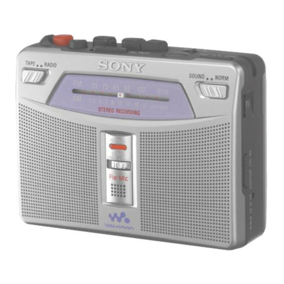
Sony WM-GX221 Service Manual
Radio cassette-corder
Hide thumbs
Also See for WM-GX221:
- Operating instructions (2 pages) ,
- Specifications (2 pages) ,
- User manual
Table of Contents
Advertisement
SERVICE MANUAL
Ver 1.2 2004.04
Frequency range
FM:
87.5-108 MHz (Italy and Saudi Arabia)
87.6-108 MHz (North, Central and South America)
87.6-107.9 MHz (Other countries)
AM:
526.5-1 606.5 kHz (Italy and Saudi Arabia)
530-1 710 kHz (North, Central and South America)
531-1 602 kHz (Other countries)
Frequency response
Input
Output
Power requirements
Dimensions (w/h/d)
Mass
Supplied accessories
Design and specifications are subject to change without notice.
Sony Corporation
9-873-412-03
2004D16-1
Personal Audio Company
© 2004.04
Published by Sony Engineering Corporation
WM-GX221
Model Name Using Similar Mechanism
Tape Transport Mechanism Type
SPECIFICATIONS
Playback: 40 - 15 000 Hz
Recording: 100 - 8 000 Hz (when
setting 2x REC TIME to NORM)
Microphone (MIC) jack
Headphones ( i ) jack
Load impedance 8 - 300 Ω
×
3 V DC batteries R6 (size AA)
2
External DC 3V power sources
×
×
Approx. 112.0
82.5
38.0 mm
×
×
(4
1
/
3
1
/
1
1
/
inches), excl.
2
4
2
projecting parts and controls
Approx. 190 g (6.8oz) (main unit
only)
Stereo headphones or earphones (1)
Stereo microphone (1)
Carrying case (1)
Battery life (Approx. hours)
Sony alkaline LR6(SG) ** Sony R6P(SR)
(using headphones/earphones)
playback
24
radio
48
mic recording
20
radio recording
12
(using the speakers)
playback
15
radio
26
radio recording
11.5
* Measured value by the standard of JEITA (Japan
Electronics and Information Technology Industries
Association) (using a Sony HF series cassette tape).
**When using Sony LR6(SG) "STAMINA" alkaline dry
batteries (produced in Japan).
Note
• The battery life may be shorter depending on the
operating condition, the surrounding temperature
and battery type.
RADIO CASSETTE-CORDER
US Model
Canadian Model
E Model
Chinese Model
New
MT-WMGX221-175
(JEITA*)
7
15
4.5
3
4.5
6
3
Advertisement
Table of Contents

Related Manuals for Sony WM-GX221


Summary of Contents for Sony WM-GX221
- Page 1 × × inches), excl. Electronics and Information Technology Industries projecting parts and controls Association) (using a Sony HF series cassette tape). **When using Sony LR6(SG) “STAMINA” alkaline dry Mass Approx. 190 g (6.8oz) (main unit batteries (produced in Japan). only)
-
Page 2: Table Of Contents
WM-GX221 TABLE OF CONTENTS 1. SERVICE NOTE ··············································································· 3 2. GENERAL ·························································································· 4 3. DISASSEMBLY ················································································ 5 3-1. Panel (Cabinet Front), Cabinet (Front) Assy ·································· 5 3-2. MAIN Board, Mechanism Deck (MT-WMGX221-175) ················ 6 3-3. HE901, HRP901, M601, Belts ························································ 7 3-4. -
Page 3: Service Note
WM-GX221 SECTION 1 SERVICE NOTE In this set, record/play mode is detected using the switch S704 (TAPE POWER). S704 is mounted on the MAIN board. If MAIN board is removed, it becomes impossible to detect record/play mode. Where MAIN board is removed, when you measure operation and voltage of each part of the mechanism deck, please turn on S704. -
Page 4: General
WM-GX221 SECTION 2 GENERAL This section is extracted from instruction manual. • LOCATION OF CONTROLS M FF/CUE TUNING m REW/REVIEW PAUSE N PLAY** BAND (FM/AM) x STO P SOUND BOOST (OFF/ON) z REC VOL * AVLS (NORM/LIMIT) SPEAKER/ i DC IN 3V NORM/CrO2 /METAL•... -
Page 5: Disassembly
WM-GX221 SECTION 3 DISASSEMBLY Note : Disassemble the unit in the order as shown below. Panel (cabinet front), Cabinet (front) assy SUB board MAIN board, Mechanism deck (MT-WMGX221-175) HE901, HRP901, M601, Belts Note : Follow the disassembly procedure in the numerical order given. -
Page 6: Main Board, Mechanism Deck (Mt-Wmgx221-175)
WM-GX221 3-2. MAIN BOARD, MECHANISM DECK (MT-WMGX221-175) cassette holder sub assy spring (torsion) three screws (B1.7 × 9) cabinet center MT-WMGX221-175 joint cover <Caution of the pointer attachment> The pointer is slid, even a stopper is brougth near, and CV1 is turned with all its might clockwise, and is attached. -
Page 7: He901, Hrp901, M601, Belts
WM-GX221 3-3. HE901, HRP901, M601, BELTS 0 screw two screws HRP901 (REC/PB head) Attaching belt (CAP) and belt (pulley). HE901 (erase head) washer M601 (stopper N) (capstan/reel washer motor) 5 washer belt (CAP) 6 capstan fly assy (AR) two screws (M1.4) belt (CAP) 3-4. -
Page 8: Mechanical Adjustment
WM-GX221 SECTION 4 SECTION 5 MECHANICAL ADJUSTMENT ELECTRICAL ADJUSTMENT PRECAUTION PRECAUTION Clean the following parts with a denatured-alcohol-moistened Specified voltage: 2.5 V (DC) swab: Switch and control position record/playback/erase head pinch roller : MAX rubber belts capstan SPEAKER : OFF... - Page 9 WM-GX221 Ver 1.1 2002.06 • Repeat the procedures in each adjustment several times. TUNER SECTION 0dB=1µV AM FREQUENCY COVERAGE ADJUSTMENT [AM] Adjust for a maximum reading on level meter. BAND : AM 505 kHz (516.5 kHz) CT1-4 1,760 kHz [1,690 kHz] (1,631.5 kHz)
-
Page 10: Diagrams
WM-GX221 Ver 1.2 SECTION 6 DIAGRAMS Note on Schematic Diagram: Note on Printed Wiring Board: • All capacitors are in µF unless otherwise noted. p: pF. • Y : parts extracted from the conductor side. 50 WV or less are not indicated except for electrolytics and •... -
Page 11: Block Diagram - Tuner Section
WM-GX221 Ver 1.2 6-1. BLOCK DIAGRAM – TUNER SECTION – S1 (1/2) US, CND, 5E LOCAL EXCEPT US, CND, 5E • SIGNAL PATH FM ST MONO : FM : AM EXCEPT US, CND, 5E 10.7MHz TU VCC FM/AM RF AMP, FM/AM MIX AMP,... -
Page 12: Block Diagram - Main Section
WM-GX221 6-2. BLOCK DIAGRAM – MAIN SECTION – D401 TU L, TU R REC/BATT TU L TU R IC501 (1/2) Q453 IC501 (2/2) MAIN VCC REC/PB AMP SWITCH MIC AMP, ALC IC151 POWER AMP J501 (PLUG IN POWER) IN (L) -
Page 13: Printed Wiring Boards
WM-GX221 Ver 1.2 6-3. PRINTED WIRING BOARDS –1 –2 SOUND BOOST Q707 /REEL IC301 IC151 IC501 • Semiconductor Location Ref. No. Location Ref. No. Location Q502 D401 C-12 Q551 D701 Q552 EXCEPT Q553 US, CND, 5E Q601 US, CND, 5E... -
Page 14: Schematic Diagram - Main Board (1/2)
WM-GX221 Ver 1.2 6-4. SCHEMATIC DIAGRAM – MAIN BOARD (1/2) – • Refer to page 10 for Waveforms. • Refer to page 16 for IC Block Diagram. (US, CND, EA, 5E) (DOUBLE) (DOUBLE) IC B/D 470p 220p 3.3k 0.022... -
Page 15: Schematic Diagram - Main Board (2/2)
WM-GX221 Ver 1.2 6-5. SCHEMATIC DIAGRAM – MAIN BOARD (2/2) – • Refer to page 16 for IC Block Diagrams. US, CND, 5E EXCEPT US, CND, 5E (US, CND) (US, CND, 5E) EXCEPT US, CND, 5E (US, CND, EA, 5E) -
Page 16: Ic Block Diagrams
WM-GX221 6-6. IC BLOCK DIAGRAMS IC151 LM4863MT IC1 TA2111FN (EL) CONTROL AM-RF IN FM-RF OUT VCC 1 FM OSC AM OSC DET-OUT MPX-IN BAND MO-ST L OUT R OUT SHUTDOWN HP-IN CIRCUIT +OUT A +OUT B DECODE BUFF DIVIDE -OUT A... -
Page 17: Exploded Views
WM-GX221 Ver 1.2 SECTION 7 EXPLODED VIEWS NOTE: • -XX, -X mean standardized parts, so they may • The mechanical parts with no reference number • Abbreviation have some differences from the original one. in the exploded views are not supplied. -
Page 18: Cabinet (Front) Section
WM-GX221 Ver 1.2 7-2. CABINET (FRONT) SECTION MIC501 SP151 SP251 Ref. No. Part No. Description Remarks Ref. No. Part No. Description Remarks 3-237-123-01 WINDOW (DIAL) (EA) 3-237-125-01 LID, BATTERY CASE 3-237-123-11 WINDOW (DIAL) (E, 9E, CH, TW) 3-237-129-01 KNOB (SP/HP) -
Page 19: Mechanism Deck Block-1 (Mt-Wmgx221-175)
WM-GX221 7-3. MECHANISM DECK BLOCK-1 (MT-WMGX221-175) A (Included in Ref. No.151) supplied HE901 HRP901 supplied M601 Ref. No. Part No. Description Remarks Ref. No. Part No. Description Remarks 3-704-197-01 SCREW (M1.4), SPECIAL HEAD 3-234-861-01 GUIDE (ARO), TAPE 3-234-857-01 BELT (CAP) -
Page 20: Mechanism Deck Block-2 (Mt-Wmgx221-175)
WM-GX221 7-4. MECHANISM DECK BLOCK-2 (MT-WMGX221-175) (Including Ref. No. Part No. Description Remarks Ref. No. Part No. Description Remarks X-3381-206-1 CHASSIS ASSY (ARO) 3-229-064-01 WASHER, STOPPER 3-225-385-01 GEAR (B) 3-225-393-01 LEVER (SHUT/OFF) 3-229-063-01 SPRING (UD) (R), COMPRESSION 3-321-813-71 WASHER, COTTER POLYETHYLENE... -
Page 21: Electrical Parts List
WM-GX221 Ver 1.2 SECTION 8 MAIN ELECTRICAL PARTS LIST NOTE: • Due to standardization, replacements in the • CAPACITORS: When indicating parts by reference number, uF: µF parts list may be different from the parts please include the board name. - Page 22 WM-GX221 Ver 1.2 MAIN Ref. No. Part No. Description Remarks Ref. No. Part No. Description Remarks C263 1-107-826-11 CERAMIC CHIP 0.1uF 10.00% 16V C606 1-115-467-11 CERAMIC CHIP 0.22uF 10.00% 10V C264 1-162-970-11 CERAMIC CHIP 0.01uF C607 1-125-838-11 CERAMIC CHIP 2.2uF 6.3V...
- Page 23 WM-GX221 Ver 1.2 MAIN Ref. No. Part No. Description Remarks Ref. No. Part No. Description Remarks < TRANSISTOR > R110 1-216-821-11 METAL CHIP 1/16W R151 1-216-833-11 METAL CHIP 1/16W Q152 8-729-216-22 TRANSISTOR 2SA1162-YG-TE85L R152 1-216-851-11 METAL CHIP 330K 1/16W Q252...
- Page 24 WM-GX221 MAIN Ref. No. Part No. Description Remarks Ref. No. Part No. Description Remarks R464 1-216-801-11 METAL CHIP 1/16W < SWITCH > R466 1-216-821-11 METAL CHIP 1/16W R467 1-216-837-11 METAL CHIP 1/16W 1-692-298-11 SWITCH, SLIDE (CrO2/METAL, NORM) R501 1-216-825-11 METAL CHIP 2.2K...
- Page 25 WM-GX221 Ver 1.2 Ref. No. Part No. Description Remarks Ref. No. Part No. Description Remarks ACCESSORIES *********** 1-542-307-11 MICROPHONE 3-237-202-01 CASE, CARRYING 3-238-369-11 MANUAL, INSTRUCTION (ENGLISH, ARABIC) (EA) 3-238-369-21 MANUAL, INSTRUCTION (ENGLISH, CHINESE, KOREAN) (E) 3-238-369-31 MANUAL, INSTRUCTION (ENGLISH, CHINESE, KOREAN) (9E)
- Page 26 WM-GX221 REVISION HISTORY Clicking the version allows you to jump to the revised page. Also, clicking the version at the upper right on the revised page allows you to jump to the next revised page. Ver. Date Description of Revision 2001.11...
Need help?
Do you have a question about the WM-GX221 and is the answer not in the manual?
Questions and answers