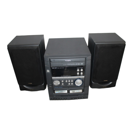
Aiwa NSX-SZ10 Service Manual
Hide thumbs
Also See for NSX-SZ10:
- Operating instructions manual (164 pages) ,
- Service manual (29 pages) ,
- Service manual (12 pages)
Table of Contents
Advertisement
SERVICE MANUAL
COMPACT DISC
STEREO SYSTEM
SYSTEM
NSX–SZ10(EZ/K)
NSX–SZ10(HR)
NSX–SZ11(LH)
NSX–SZ12(EZ)
NSX–SZ17(EZ)
• This Service Manual is the "Revision Publishing" and replaces "Simple Manual"
(S/M Code No. 09-003-424-8T1).
• If requiring information about the CD mechanism, see Service Manual of AZG-1,
(S/M Code No. 09-001-335-3NC).
NSX-SZ10
NSX-SZ11
NSX-SZ12
NSX-SZ17
BASIC TAPE MECHANISM : ZZM-2 PR1NM(10/12/17)
BASIC TAPE MECHANISM : ZZM-2 YPR1NM(11)
BASIC CD MECHANISM : AZG-1 ZA3RNDM(10/12/17)
BASIC CD MECHANISM : AZG-1 YZA3RNDM(11)
CD
CASSEIVER
CX–NSZ10
CX–NSZ10
CX–NSZ11
CX–NSZ12
CX–NSZ17
S/M Code No. 09-003-424-8R2
REMOTE
SPEAKER
CONTROLLER
SX–NSZ10
SX–NSZ12
RC–ZAS02
SX–NSZ15
SX–NSZ12
SX–NSZ10
RC–ZAS17
EZ K HR
LH
EZ
EZ
Advertisement
Table of Contents

Related Manuals for Aiwa NSX-SZ10


Summary of Contents for Aiwa NSX-SZ10
- Page 1 NSX-SZ10 EZ K HR NSX-SZ11 NSX-SZ12 NSX-SZ17 SERVICE MANUAL BASIC TAPE MECHANISM : ZZM-2 PR1NM(10/12/17) COMPACT DISC BASIC TAPE MECHANISM : ZZM-2 YPR1NM(11) STEREO SYSTEM BASIC CD MECHANISM : AZG-1 ZA3RNDM(10/12/17) BASIC CD MECHANISM : AZG-1 YZA3RNDM(11) REMOTE SYSTEM SPEAKER...
-
Page 2: Table Of Contents
TABLE OF CONTENTS SPECIFICATIONS ..........................3, 4 PROTECTION OF EYES FROM LASER BEAM DURING SERVICING/ Precaution to replace Optical block......................5 NOTE ON BEFORE STARTING REPAIR ..................6, 7 ELECTRICAL MAIN PARTS LIST ..................... 8-13 TRANSISTOR ILLUSTRATION ......................14 WIRING-1 (MAIN: K, EZ) ........................ 15, 16 SCHEMATIC DIAGRAM-1 (MAIN 1/2: K, EZ) ................. -
Page 3: Specifications
SPECIFICATIONS K, EZ MODELS HR MODEL • • Design and specifications are subject to change without Design and specifications are subject to change without notice notice... - Page 4 LH MODEL • Design and specifications are subject to change without notice...
-
Page 5: Protection Of Eyes From Laser Beam During Servicing
PROTECTION OF EYES FROM LASER BEAM DURING SERVICING This set employs laser. Therefore, be sure to follow carefully the CAUTION instructions below when servicing. Use of controls or adjustments or performance of procedures other than those specified herein may result in hazardous WARNING! radiation exposure. -
Page 6: Note On Before Starting Repair
NOTE ON BEFORE STARTING REPAIR 1. Forced discharge of electrolytic capacitor of power supply block When repair is going to be attempted in the set that uses relay circuit in the power supply block, electric potential is kept charged across the electrolytic capacitors (C101, 102) even though AC power cord is removed. - Page 7 In such a case, check also if the POWER AMPLIFIER circuit or power supply circuit has any abnormalities or not. 2-2. Regarding reset There are cases that the machine does not work correctly because the MICROCOMPUTER is not reset even though the AC power cord is re-inserted, or the software reset (pressing the STOP key + POWER key) is performed.
-
Page 8: Electrical Main Parts List
ELECTRICAL MAIN PARTS LIST REF. NO PART NO. KANRI DESCRIPTION REF. NO PART NO. KANRI DESCRIPTION 87-010-196-080 CHIP CAPACITOR,0.1-25 <EXCEPT 11LHSC2> 8A-NFA-615-010 C-IC,M38B57MCH-E236FP 87-010-196-080 CHIP CAPACITOR,0.1-25<11LHSC2> <EXCEPT 12EZ> 87-010-196-080 CHIP CAPACITOR,0.1-25<11LHSC2> 8A-NFA-616-010 C-IC,M38B59MFH-E251FP<12EZ> 87-010-196-080 CHIP CAPACITOR,0.1-25 87-A21-397-010 IC,STK490-070<11LHSC2> <EXCEPT 11LHSC2> 87-A21-482-010 IC,RPM6938-H4 87-A10-627-000... - Page 9 REF. NO PART NO. KANRI DESCRIPTION REF. NO PART NO. KANRI DESCRIPTION REF. NO PART NO. KANRI DESCRIPTION REF. NO PART NO. KANRI DESCRIPTION C112 87-010-391-080 CAP,E 10-35 SME<11LHSC2> C317 87-010-546-080 CAP, ELECT 0.33-50V<11LHSC2> C460 87-010-196-080 CHIP CAPACITOR,0.1-25<11LHSC2> C790 87-A12-052-080 C-CAP,S 0.033-25 J B<11LHSC2>...
- Page 10 REF. NO PART NO. KANRI DESCRIPTION REF. NO PART NO. KANRI DESCRIPTION REF. NO PART NO. KANRI DESCRIPTION REF. NO PART NO. KANRI DESCRIPTION C869 87-010-197-080 CAP, CHIP 0.01 DM<12EZ> C998 87-010-260-080 CAP, ELECT 47-25V<EXCEPT 11LHSC2> L944 87-A50-159-010 COIL,10MH K C2B<10HR> C120 87-012-156-080 C-CAP,S 220P-50 CH...
-
Page 11: Transistor Illustration
TRANSISTOR ILLUSTRATION REF. NO PART NO. KANRI DESCRIPTION PT C.B 87-010-403-080 CAP, ELECT 3.3-50V<10HR> 87-010-403-080 CAP, ELECT 3.3-50V<11LHSC2> C183 87-010-387-080 CAP,E 470-25 SME E C B S D G E C B B C E <10EZ,12EZ,17EZ,10K> C184 87-010-403-080 CAP, ELECT 3.3-50V <10EZ,12EZ,17EZ,10K>... -
Page 12: Wiring-1 (Main: K, Ez)
WIRING-1 (MAIN: K, EZ) EZ,K EZ,K 12EZ EZ,K EZ,K 12EZ EZ,K 12EZ MW/LW LOOP EZ,K EZ,K EZ,K EZ,K 75Ω (COAXIAL) EZ,K J602 FB602 VIDEO/ J602 EZ,K... -
Page 13: Schematic Diagram-1 (Main 1/2: K, Ez)
SCHEMATIC DIAGRAM-1 (MAIN 1/2: K, EZ) -
Page 14: Schematic Diagram-2 (Main 2/2: K, Ez)
SCHEMATIC DIAGRAM-2 (MAIN 2/2: K, EZ) -
Page 15: Wiring-2 (Main: Hr)
WIRING-2 (MAIN: HR) <HR> Q949 TC943 Q941 Q950 J940 C956 MW LOOP D941 TC941 R957 R970 D951 L952 L953 Q942 Q945 Q944 C470 C315 Q837 J602 VIDEO J602 C116 C117 R176... -
Page 16: Schematic Diagram-3 (Main 1/2: Hr)
SCHEMATIC DIAGRAM-3 (MAIN 1/2: HR) -
Page 17: Schematic Diagram-4 (Main 2/2: Hr)
SCHEMATIC DIAGRAM-4 (MAIN 2/2: HR) R964... -
Page 18: Wiring-3 (Main: Lh)
WIRING-3 (MAIN: LH) -
Page 19: Schematic Diagram-5 (Main 1/2: Lh)
SCHEMATIC DIAGRAM-5 (MAIN 1/2: LH) -
Page 20: Schematic Diagram-6 (Main 2/2: Lh)
SCHEMATIC DIAGRAM-6 (MAIN 2/2: LH) -
Page 21: Wiring-4 (Front)
WIRING-4 (FRONT) D301 D302 D303 D304 D305 EZ/K 12EZ : MOUNT : NO MOUNT 12EZ MODEL... -
Page 22: Schematic Diagram-7 (Front)
SCHEMATIC DIAGRAM-7 (FRONT) D301 D302 D303 D304 D305 EZ/K 12EZ 12EZ MODEL HR MODEL OTHER MODELS LH MODEL # : NO MOUNT... -
Page 23: Wiring-5 (Pt: K, Ez)
WIRING-5 (PT: K, EZ) SCHEMATIC DIAGRAM-8 (PT: K, EZ) <K/EZ> AC 230V 50Hz AC 230V 50Hz... -
Page 24: Wiring-6 (Pt: Hr)
WIRING-6 (PT: HR) SCHEMATIC DIAGRAM-9 (PT: HR) AC 120V 220V/230V/240V 50/60Hz... -
Page 25: Wiring-7 (Pt: Lh)
WIRING-7 (PT: LH) SCHEMATIC DIAGRAM-10 (PT: LH) C PT C.B <LH> AC 120V 220V/230V/240V 50/60Hz... -
Page 26: Fl (10-Bt-224Gnk) Grid Assignment/Anode Connection
WIRING-8 (DECK) FL (10-BT-224GNK) GRID ASSIGNMENT/ANODE CONNECTION GRID ASSIGNMENT... - Page 27 ANODE CONNECTION...
-
Page 28: Ic Block Diagram
IC BLOCK DIAGRAM IC, LC72131D IC, M62495AFP... - Page 29 IC, LA1843/LA1844L-A RF. AMP BUFF PILOT DECODER ANTI-BIRDIE CANCEL P-DET STEREO Ø AM/FM LEVEL COMP S-CURVE π PILOT BUFF 304kHz TUNING DRIVE IC, BU1920FS 100kΩ 8TH SWITCHED CAPACITOR FILTER Vref RCLK QUAR RESET BI-PHASE DIFFERENTIAL RDATA 57kHz 1187.5HZ DECODER DECODER RDS/ARI REFERENCE TEST CIRCUIT...
-
Page 30: Electrical Adjustment-1 (K, Ez)
ELECTRICAL ADJUSTMENT-1 (K, EZ) A MAIN C.B %$#@098653 1 9 6 L801 TC942 L802 TP4 (DC BAL) L941 IC801 L951 L942 IC301 (DC BAL) (CLK) TP8 (LCH) TP1 (VT) TP9 (RCH) FFE831 DECK–1 R/P/E, DECK-2 P HEAD B FRONT C.B IC101 L101... -
Page 31: Tuner Section
< TUNER SECTION > < DECK SECTION > 1. Clock Frequency Check 10. Tape Speed Adjustment (DECK 1) Settings: • Test point: TP2 (CLK) Settings: • Test tape: TTA-100 Method: Set to MW 1602kHz and check that the test point •... -
Page 32: Electrical Adjustment-2 (Hr)
ELECTRICAL ADJUSTMENT-2 (HR) A MAIN C.B %$#@098653 1 9 6 L801 L802 TC943 TP4(DC BAL) TC941 L941 IC801 L942 IC301 (DC BAL) (CLK) L953 L952 TP8 (LCH) TP1 (VT) TP9 (RCH) FFE831 DECK–1 R/P/E, DECK-2 P HEAD B FRONT C.B IC101 L101... - Page 33 < TUNER SECTION > < DECK SECTION > 1. Clock Frequency Check 10. Tape Speed Adjustment (DECK 1) Settings: • Test point: TP2 (CLK) Settings: • Test tape: TTA-100 Method: Set to MW 1602kHz and check that the test point •...
-
Page 34: Electrical Adjustment-3 (Lh)
ELECTRICAL ADJUSTMENT-3 (LH) A MAIN C.B #@!0987643 1 7 4 L801 L802 TP4 (DC BAL) IC801 L951 IC301 (DC BAL) (CLK) TP8 (LCH) TP1 (VT) TP9 (RCH) FFE831 DECK–1 R/P/E, DECK-2 P HEAD B FRONT C.B IC101 L101... - Page 35 < TUNER SECTION > 10. PB Frequency Response Check (DECK 1, DECK 2) Settings: • Test tape: TTA-330 1. Clock Frequency Check • Test point: TP8 (Lch), TP9 (Rch) Settings: • Test point: TP2 (CLK) Method: Play back the 315Hz and 8kHz signals of the test Method: Set to AM 1602kHz and check that the test point tape and check that the output ratio of the 8kHz...
-
Page 36: Ic Description
IC DESCRIPTION IC, M38B57MCH-E236FP/M38B59MFH-E250FP Pin No. Pin Name Description I-SIG RDS signal level A/D input. (Not used) I-HOLD Hold voltage level A/D input. I-SW (CD) CD mecha SW A/D input. I-DISH CD turn-table position check A/D input. I-KEY2 KEY2 A/D input. I-KEY1 KEY1 A/D input. - Page 37 Pin No. Pin Name Description O-DISH_R CD turn-table reverse turn output. O-DISH_F CD turn-table forward turn output. I-SUBQ Sub code-Q data input. O-CD_CE CD DSP chip enable output. I-WRQ CD WRQ input. O-CLK (CD) CD control clock output . O-DATA (CD) CD control data output.
-
Page 38: Mechanical Parts List 1/1
WINDOW,CASS 1<EXCEPT 17EZBM> 29 8A-NFA-025-010 CABI,REAR EZSM SZ12<12 EZSM> 5 8A-NFA-071-010 WINDOW,CASS 1 BLK<17EZBM> 29 8A-NFA-022-010 CABI,REAR HRJSM<10HR> 6 87-CE3-023-010 BADGE,AIWA 30N SILV 29 8A-NFA-026-010 CABI,REAR KSM<10KSM> 7 8A-NFA-054-010 WINDOW,DISP EZ SZ12<12 EZSM> 29 8A-NFA-030-010 CABI,REAR LH W/O SPEC<11LHSC> 7 8A-NFA-059-010 WINDOW,DISP EZ SZ17<17EZBM>... -
Page 39: Mechanical Exploded View 1/1
MECHANICAL EXPLODED VIEW 1/1 AZG-1 LHSC2M P.C.B HT-SINK P.C.B ZZM-2 P.C.B LHSC2M HLDR1 HT-SINK PLATE EARTH HRJSM/ HLDR2 HRJSM MECHA LHSC2M PLATE EARTH MIC P.C.B BINDER CHAS, MAIN WIRE... -
Page 40: Tape Mechanism Exploded View 1/1 (Zzm-2 Pr1Nm/Pr1No/Ypr1Nm)
TAPE MECHANISM EXPLODED VIEW 1/1 (ZZM-2 PR1NM/PR1NO/YPR1NM) TERMINAL,LB1 TERMINAL,LB1... -
Page 41: Tape Mechanism Parts List 1/1 (Zzm-2 Pr1Nm/Pr1No/Ypr1Nm)
TAPE MECHANISM PARTS LIST 1/1 (ZZM-2 PR1NM/PR1NO/YPR1NM) REF. NO PART NO. KANRI DESCRIPTION REF. NO PART NO. KANRI DESCRIPTION 1 8Z-ZM1-254-210 SPR-C,REEL R 36 8Z-ZM1-220-110 LEVER,REC SENSOR 2 8Z-ZM1-225-110 GEAR,REEL R 37 8Z-ZM1-249-010 SPR-T,FR 3 8Z-ZM1-253-110 SPR-C,AUTO SENSOR 38 8Z-ZM1-242-110 SPR-T,FF/REW 4 8Z-ZM1-217-110 LEVER,AUTO SENSOR... -
Page 42: Speaker Disassembly Instructions
SPEAKER DISASSEMBLY INSTRUCTIONS Type.1 Type.4 Insert a flat-bladed screwdriver into the position indicated by the TOOLS arrows and remove the panel. Remove the screws of each speaker 1 Plastic head hammer unit and then remove the speaker units. 2 (-) flat head screwdriver 3 Cut chisel How to Remove the PANEL, FR Type.2... -
Page 43: Speaker Parts List 1/1
SPEAKER PARTS LIST 1/1 REF. NO PART NO. KANRI DESCRIPTION 1 8A-NSL-001-010 PANEL,FR<EXCEPT 10YB> 1 8A-NSL-012-010 PANEL,FR B<10YB> 2 8A-NSL-003-010 GRILLE,FRAME ASSY 3 8A-NSL-606-010 SPKR, W 120<10YS,10YB,12Y1S,12YS> 3 8A-NSL-604-010 SPKR, W 120<12YJ3S,12YJSC1> 3 8Z-NSL-603-010 SPKR, W 120<12YJSL,12YJSC> 3 8A-NSL-602-010 SPKR,120<15YLSC> 4 8A-NSL-017-010 CORD,SPKR <12Y1S,12YS,12YJ3S,15YLSC>... - Page 44 2–11, IKENOHATA 1–CHOME, TAITO-KU, TOKYO 110, JAPAN TEL:03 (3827) 3111 Printed in Singapore 920074...