Table of Contents
Advertisement
Quick Links
SmartSense
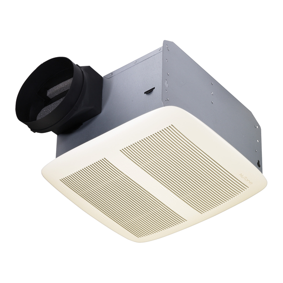
MODEL: QT110H
SUITABLE FOR USE OVER TUB OR SHOWER ENCLOSURE
WHEN INSTALLED IN A GFCI PROTECTED BRANCH CIRCUIT.
IMPORTANT SAFETY INSTRUCTIONS
WARNING: TO REDUCE THE RISK OF FIRE. ELECTRIC SHOCK,
OR INJURY TO PERSONS, OBSERVE THE FOLLOWING:
A. Use this unit only in the manner intended by the manufacturer. If you
have questions, contact the manufacturer.
B. Before servicing or cleaning unit, switch power off at service
panel and lock service panel to prevent power from being
switched on accidentally.
When the service disconnecting means cannot be locked, securely
fasten a prominent warning device, such as a tag, to the service
panel.
CAUTION:
For general ventilating use only. Do not use to exhaust hazardous
or explosive materials and vapors.
INSTALLATION INSTRUCTIONS
WARNING: TO REDUCE THE RISK OF FIRE, ELECTRIC SHOCK,
OR INJURY TO PERSONS, OBSERVE THE FOLLOWING:
A. Installation work and electrical wiring must be done by qualified
person(s) in accordance with all applicable codes and standards,
including fire-rated construction.
B. Sufficient air is needed for proper combustion and exhausting of
gases through the flue (chimney) of fuel burning equipment to prevent
back drafting. Follow the heating equipment manufacturer's guideline
and safety standards such as those published by the National Fire
Protection Association (NFPA), and the American Society for
Heating, Refrigeration and Air Conditioning Engineers (ASHRAE),
and the local code authorities.
C. When cutting or drilling into wall or ceiling, do not damage electrical
Wiring and other hidden utilities.
D. Ducted fans must always be vented to the outdoors.
E. If this unit is to be installed over a tub or shower, it must be marked
as appropriate for the application and be connected to a GFCI
(Ground Fault Circuit Interrupter) - protected branch circuit.
F. NEVER place a switch where it can be reached from a tub or shower.
G. Handle the sensor unit with care. Avoid direct contact with electronic
components while installing.
•
Do not install in a ceiling insulated to a value greater than R40.
•
Not for use in kitchens.
FOR BEST RESULTS
When installing the Ventilator in a new construction site, install
housing during the rough-in construction of the building. The blower unit,
sensor unit and grille should be installed after the finished ceiling is in
place.
To install a ventilator in an existing building requires an accessible
area (attic or crawl space) above the planned location.
This unit is designed to detect increased humidity levels and to
automatically activate the fan. For best results, the fan should be located
near the humidity source. Increasing the distance from the source will
lengthen the response time of the unit.
Combination
™
4" DIAMETER DUCT
(CONDUIT DE 4 PO DE DIAMÉTRE)
CEILING INSTALLATION
(POSE AU PLAFOND)
INSTALLATION IN A NEW CONSTRUCTION SITE
PREPARATION
1. Remove blower/power unit assembly from housing:
A. If necessary, unplug power unit.
B. Loosen three (3) mounting screws.
C. Slide unit back to free it from mounting screws.
D. Remove unit and set aside until needed.
2. Remove one of the wiring knockouts from housing.
MOUNTING THE HOUSING
1. Refer to Figure 4. Insert mounting brackets at each end of housing.
2. Place long side of housing parallel to ceiling joist. Position housing in
desired location. Make sure housing flange is even with the planned
finished ceiling.
3. Use screws or nails (not provided) to secure mounting brackets to
ceiling joists.
4. Refer to Figure 1. Use 4" round duct to discharge the ventilator to the
outside.
IMPORTANT: Be sure nothing obstructs the discharge of the
ventilator. Make sure that insulation does not get into the duct work
or into the fan.
INSTALLATION INSTRUCTIONS
READ & SAVE THESE INSTRUCTIONS!
90° ELBOW
(COUDE À 90°)
ROOF CAP
(COUVERCLE DE TOÎT)
WALL CAP
(COUVERCLE MURAL)
FIGURE 1
Advertisement
Table of Contents

Related Manuals for NuTone SmartSense QT110H


Summary of Contents for NuTone SmartSense QT110H
- Page 1 INSTALLATION INSTRUCTIONS READ & SAVE THESE INSTRUCTIONS! SmartSense Combination ™ MODEL: QT110H SUITABLE FOR USE OVER TUB OR SHOWER ENCLOSURE WHEN INSTALLED IN A GFCI PROTECTED BRANCH CIRCUIT. IMPORTANT SAFETY INSTRUCTIONS WARNING: TO REDUCE THE RISK OF FIRE. ELECTRIC SHOCK, OR INJURY TO PERSONS, OBSERVE THE FOLLOWING: ROOF CAP A.
- Page 2 CONNECTOR BLACK BLACK 120 VOLT AC SUPPLY WHITE WHITE JUNCTION BOX COVER MOTOR PLUG JUNCTION BOX WIRING CONNECTIONS FIGURE 2 SENSOR COVER TABS WIRING Refer Figure 2. 1. Run 120v AC house power wiring (with ground) through switch box to junction box in ventilator housing.
- Page 3 SENSOR CLEANING WIRING KNOCKOUT DISCHARGE OPENING (OUVERTURE DE DÉCHARGE (DÉBOUCHURE) The humidity sensor is permanently mounted in the control unit and is visible in one corner of the ventilator behind the grille. HOUSING Periodically check and clean the sensor as follows: (BOÌTIER) MOUNTING 1.
- Page 4 WARRANTIES OF MERCHANTABILITY OR FITNESS FOR A PARTICULAR PURPOSE. During this one year period, NuTone will, at its option, repair or replace, without charge, any product or part which is found to be defective under normal use and service. THIS WARRANTY DOES NOT EXTEND TO FLUORESCENT LAMP STARTERS OR TUBES, FILTERS, DUCT, ROOF CAPS, WALL CAPS AND OTHER ACCESSORIES FOR DUCTING.
Need help?
Do you have a question about the SmartSense QT110H and is the answer not in the manual?
Questions and answers