Table of Contents
Advertisement
This service information is designed for experienced repair technicians only and is not designed for use by the general public.
It does not contain warnings or cautions to advise non-technical individuals of potential dangers in attempting to service a product.
Products powered by electricity should be serviced or repaired only by experienced professional technicians. Any attempt to
service or repair the products dealt with in this service information by anyone else could result in serious injury or death.
In order to avoid frostbite, be assured of no refrigerant leakage during the installation or repairing of refrigerant circuit.
TABLE OF CONTENTS
1. Safety Precautions.............................................3
2. Specification .......................................................5
3. Location of Controls and Components ...........7
3.1
Indoor Unit....................................................7
3.2
Outdoor Unit .................................................7
3.3
Remote Control ............................................7
4. Dimensions .........................................................8
4.1
Indoor Unit....................................................8
4.2
Outdoor Unit .................................................9
5. Refrigeration Cycle Diagram...........................10
6. Block Diagram ..................................................11
7. Wiring Connection Diagram............................12
7.1
Indoor Unit..................................................12
7.2
Outdoor Unit ...............................................13
8. Electronic Circuit Diagram ..............................14
8.1
Indoor Unit..................................................14
8.2
Outdoor Unit ...............................................15
WARNING
PRECAUTION OF LOW TEMPERATURE
9. Printed Circuit Board .......................................16
10. Installation Instruction.....................................19
11. Operation Control.............................................27
12. Protection Control............................................31
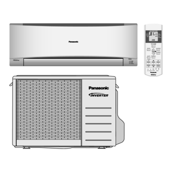
Indoor Unit
CS-S9NKUA
CS-S12NKUA
9.1
Indoor Unit..................................................16
9.2
Outdoor Unit ...............................................18
10.1
S9NKUA S12NKUA...................................19
11.1
Basic Function............................................27
11.2
Indoor Fan Motor Operation.......................28
and S12NK)................................................28
11.4
Airflow Direction .........................................28
of Dry Mode)...............................................29
11.6
Powerful Mode Operation ..........................30
11.7
Timer Control..............................................30
11.8
Random Auto Restart Control ....................30
11.9
Indication Panel..........................................30
© Panasonic HA Air-Conditioning (M) Sdn. Bhd. 2011.
Unauthorized copying and distribution is a violation of law.
Order No: PHAAM1111085C1
Outdoor Unit
CU-S9NKUA
CU-S12NKUA
Advertisement
Table of Contents
Troubleshooting

Related Manuals for Panasonic CS-S9NKUA


Summary of Contents for Panasonic CS-S9NKUA
-
Page 1: Table Of Contents
Random Auto Restart Control ....30 Outdoor Unit ..........13 11.9 Indication Panel..........30 8. Electronic Circuit Diagram ......14 12. Protection Control..........31 Indoor Unit..........14 Outdoor Unit ..........15 © Panasonic HA Air-Conditioning (M) Sdn. Bhd. 2011. Unauthorized copying and distribution is a violation of law. - Page 2 12.1 Restart Control (Time Delay Safety Control)..............31 12.2 30 Seconds Forced Operation ....31 12.3 Total Running Current Control ....31 12.4 IPM (Power Transistor) Prevention Control31 12.5 Low Pressure Protection Control (Gas Leakage Detection) ........32 12.6 Low Frequency Protection Control 1 ..32 12.7 Low Frequency Protection Control 2 ..32 12.8...
-
Page 3: Safety Precautions
1. Safety Precautions • Read the following “SAFETY PRECAUTIONS” carefully before perform any servicing. • Electrical work must be installed or serviced by a licensed electrician. Be sure to use the correct rating of the power plug and main circuit for the model installed. •... - Page 4 WARNING During installation, install the refrigerant piping properly before run the compressor. (Operation of compressor without fixing refrigeration piping and valves at opened condition will cause suck-in of air, abnormal high pressure in refrigeration cycle and result in explosion, injury etc.).
-
Page 5: Specification
2. Specification Indoor CS-S9NKUA CS-S12NKUA Model Outdoor CU-S9NKUA CU-S12NKUA Performance Test Condition Phase, Hz Single, 60 Single, 60 Power Supply Min. Mid. Max. Min. Mid. Max. Min. Mid. Max. Min. Mid. Max. 1.20 2.49 3.00 1.20 2.49 3.00 1.20 3.51 3.90... - Page 6 Control Device Capillary Tube Capillary Tube Refrigeration Refrigerant Oil FV50S (320) FV50S (320) Cycle Refrigerant Type g (oz) R410A, 980 (34.6) R410A, 980 (34.6) Height(I/D / O/D) mm (inch) 290 (11-7/16) / 540 (21-9/32) 290 (11-7/16) / 540 (21-9/32) Dimension Width (I/D / O/D) mm (inch) 870 (34-9/32) / 780 (30-23/32)
-
Page 7: Location Of Controls And Components
3. Location of Controls and Components Indoor Unit Outdoor Unit Remote Control... -
Page 8: Dimensions
4. Dimensions Indoor Unit... -
Page 9: Outdoor Unit
Outdoor Unit... -
Page 10: Refrigeration Cycle Diagram
5. Refrigeration Cycle Diagram INDOOR OUTDOOR LIQUID EXP . PROCESSTUBE DISCHARGE SIDE STRAINER VALVE MUFFLER 2-WAY VALVE PIPE TEMP. SENSOR INTAKE TEMP. SENSOR HEAT EXCHANGER (EVAPORATOR) F.COND 4-WAY VALVE SIDE 4-WAY VALVE DISCHARGE MUFFLER ACCUMULATOR COMP. COOLING HEATING... -
Page 11: Block Diagram
6. Block Diagram... -
Page 12: Wiring Connection Diagram
7. Wiring Connection Diagram Indoor Unit... -
Page 13: Outdoor Unit
Outdoor Unit... -
Page 14: Electronic Circuit Diagram
8. Electronic Circuit Diagram Indoor Unit... -
Page 15: Outdoor Unit
Outdoor Unit... -
Page 16: Printed Circuit Board
9. Printed Circuit Board Indoor Unit 9.1.1 Main Printed Circuit Board... - Page 17 9.1.2 Power Printed Circuit Board 9.1.3 Indicator Printed Circuit Board...
-
Page 18: Outdoor Unit
Outdoor Unit 9.2.1 Main Printed Circuit Board... -
Page 19: Installation Instruction
10. Installation Instruction 10.1 S9NKUA S12NKUA 10.1.1 Select the Best Location 10.1.2 Indoor/Outdoor Unit Installation Diagram 10.1.1.1 Indoor Unit • Do not install the unit in excessive oil fume area such as kitchen, workshop and etc. • There should not be any heat source or steam near the unit. -
Page 20: How To Fix Installation Plate
10.1.3 Indoor Unit 10.1.3.1 How to Fix Installation Plate The mounting wall shall be strong and solid enough to prevent if from the vibration. The centre of installation plate should be at more than at right and left of the wall. The distance from installation plate edge to ceiling should more than From installation plate left edge to unit’s left side is From installation plate right edge to unit’s right side is... - Page 21 10.1.3.3 Indoor Unit Installation 10.1.3.4 For the right rear piping 10.1.3.5 For the right bottom piping 10.1.3.6 For the embedded piping (This can be used for left rear piping and bottom piping also.)
- Page 22 10.1.3.7 Connect the Cable to the Indoor Unit 1. The inside and outside connection cable can be connected without removing the front grille. 2. Unscrew the conduit cover and fix the conduit connector to conduit cover with lock nut, then secure it against chassis.
- Page 23 10.1.3.8 Wire Stripping and connecting requirement 10.1.3.9 Cutting and flaring the piping Please cut using pipe cutter and then remove the burrs. Remove the burrs by using reamer. If burrs is not removed, gas leakage may be caused. Turn the piping end down to avoid the metal powder entering the pipe.
-
Page 24: Install The Outdoor Unit
10.1.4 Outdoor Unit 10.1.4.1 Install the Outdoor Unit • After selecting the best location, start installation to Indoor/Outdoor Unit Installation Diagram. Fix the unit on concrete or rigid frame firmly and horizontally by bolt nut (ø13/32”). When installing at roof, please consider strong wind and earthquake. Please fasten the installation stand firmly with bolt or nails. - Page 25 10.1.4.3 Evacuation of the equipment WHEN INSTALLATION AN AIR CONDITIONER, BE SURE TO EVACUATE THE AIR INSIDE THE INDOOR UNIT AND PIPES in the following procedures. 1. Connect a charging hose with a push pin to the Low side of a charging set and the service port of the 3-way valve.
- Page 26 9. Secure the wire onto the control board with the holder (clamper). 10. After completing wiring connections, reattach the control board cover (Metal and Resin) and the top panel to the original position with the screws. 11. For wire stripping and connection requirement, refer to instruction of indoor unit.
-
Page 27: Operation Control
11. Operation Control 11.1 Basic Function Inverter control, which equipped with a microcomputer in determining the most suitable operation mode as time passes, automatically adjusts output power for maximum comfort always. In order to achieve the suitable operation mode, the microcomputer maintains the set temperature by measuring the temperature of the environment and performing temperature shifting. -
Page 28: Indoor Fan Motor Operation
11.2 Indoor Fan Motor Operation 11.2.1 Basic Rotation Speed • Manual Fan Speed Fan motor’s number of rotation is determined according to remote control setting. Remote control ○ ○ ○ ○ ○ • Auto Fan Speed According to room temperature and setting temperature, indoor fan speed is determined automatically. The indoor fan will operate according to pattern below. -
Page 29: Quiet Operation (Cooling Mode/Cooling Area Of Dry Mode)
11.4.1 Vertical Airflow Vane Angle (°) Operation Mode Airflow Direction Auto 20 ~ 45 Cooling Manual Auto 20 ~ 45 Soft Dry Manual • Automatic vertical airflow direction can be set using remote control; the vane swings up and down within the angles as stated above. -
Page 30: Powerful Mode Operation
11.6 Powerful Mode Operation • When the powerful mode is selected, the internal setting temperature will shift lower up to 35.6°F (for Cooling/Soft Dry) than remote control setting temperature for 20 minutes and the fan speed will increase to achieve the setting temperature quickly. •... -
Page 31: Protection Control
12. Protection Control 12.1 Restart Control (Time Delay Safety Control) • The compressor will not turn on within 3 minutes from the moment operation stops, although the unit is turned on again by pressing OFF/ON button at remote control within this period. •... -
Page 32: Low Pressure Protection Control (Gas Leakage Detection)
12.5 Low Pressure Protection Control (Gas Leakage Detection) • Control start conditions For 5 minutes, the compressor continously operates and outdoor total current is between 0.64A and 0.85A During Cooling and Soft Dry operation: Indoor suction temperature – indoor piping temperature is below 39.2°F •... -
Page 33: Freeze Prevention Control
12.10 Freeze Prevention Control • When indoor heat exchanger temperature is lower than 32°F continuously for 6 minutes, compressor will stops operation. • Compressor will resume its operation 3 minutes after the indoor heat exchanger is higher than 55.4°F. • At the same time, indoor fan speed will be higher than during its normal operation. -
Page 34: Servicing Mode
13. Servicing Mode 13.1 Auto Off/On Button Auto OFF/ON Auto OFF/ON Button Pressed Button Pressed 5 sec Auto Operation Test Run Operation Stop (Forced Cooling Operation) AUTO OPERATION MODE The Auto Operation will be activated immediately once the Auto OFF/ON button is pressed. This operation can be used to operate air conditioner with limited function if remote control is misplaced or malfunction. -
Page 35: Remote Control Button
13.2 Remote Control Button 13.2.1 SET Button • To check remote control transmission code and store the transmission code to EEPROM Press “Set” button continuously for 10 seconds by using pointer Press “Timer Set” button unit a “beep” sound is heard as confirmation of transmission code change. 13.2.2 RESET (RC) •... -
Page 36: Troubleshooting Guide
14. Troubleshooting Guide 14.1 Refrigeration Cycle System In order to diagnose malfunctions, ensure the air conditioner is free Normal Pressure and Outlet Air Temperature (Standard) from electrical problems before inspecting the refrigeration cycle. Gas Pressure Outlet air Temperature Such problems include insufficient insulation, problem with the (kg/cm (°F) power source, malfunction of a compressor and a fan. - Page 37 14.1.1 Relationship between the condition of the air conditioner and pressure and electric current Cooling Mode Condition of the air conditioner Low Pressure High Pressure Electric current during operation Insufficient refrigerant (gas leakage) Clogged capillary tube or strainer Short circuit in the indoor unit Heat radiation deficiency of the outdoor unit Inefficient compression...
-
Page 38: Breakdown Self Diagnosis Function
14.2 Breakdown Self Diagnosis Function 14.2.1 Self Diagnosis Function (Three Digits Alphanumeric Code) • Once error occurred during operation, the unit will stop its operation, and Timer LED blinks. • Although Timer LED goes off when power supply is turned off, if the unit is operated under a breakdown condition, the LED will ON again. -
Page 39: Error Code Table
14.3 Error Code Table Diagnosis Emergency Abnormality / Protection control Abnormality Judgment Primary location to verify display Operation No abnormality detected Normal operation • Internal / external cable connection Indoor / Outdoor abnormal > 1 min after starting Indoor fan operation communication operation only... -
Page 40: Troubleshooting Flowchart
14.4 Troubleshooting Flowchart 14.4.1 H11 (Indoor/Outdoor Abnormal Communication) Malfunction Decision Conditions • During startup and operation of cooling and heating, the data received from outdoor unit in indoor unit signal transmission is checked whether it is normal. Malfunction Caused • Faulty indoor unit PCB. - Page 41 14.4.2 H12 (Indoor/Outdoor Capacity Rank Mismatched) Malfunction Decision Conditions • During startup, error code appears when different types of indoor and outdoor units are interconnected. Malfunction Caused • Wrong models interconnected. • Wrong indoor unit or outdoor unit PCBs mounted. •...
- Page 42 14.4.3 H14 (Indoor Intake Air Temperature Sensor Abnormality) Malfunction Decision Conditions • During startup and operation of cooling and heating, the temperatures detected by the indoor intake air temperature sensor are used to determine sensor errors. Malfunction Caused • Faulty connector connection. •...
- Page 43 14.4.4 H15 (Compressor Temperature Sensor Abnormality) Malfunction Decision Conditions • During startup and operation of cooling and heating, the temperatures detected by the outdoor compressor temperature sensor are used to determine sensor errors. Malfunction Caused • Faulty connector connection. • Faulty sensor.
- Page 44 14.4.5 H16 (Outdoor Current Transformer Open Circuit) Malfunction Decision Conditions • A current transformer (CT) is detected by checking the compressor running frequency (≥ rated frequency) and CT detected input current (less than 1.14A) for continuously 20 seconds. Malfunction Caused •...
- Page 45 14.4.6 H19 (Indoor Fan Motor – DC Motor Mechanism Locked) Malfunction Decision Conditions • The rotation speed detected by the Hall IC during fan motor operation is used to determine abnormal fan motor (feedback of rotation > 2550rpm or < 50rpm) Malfunction Caused •...
- Page 46 14.4.7 H23 (Indoor Pipe Temperature Sensor Abnormality) Malfunction Decision Conditions • During startup and operation of cooling and heating, the temperatures detected by the indoor heat exchanger temperature sensor are used to determine sensor errors. Malfunction Caused • Faulty connector connection. •...
- Page 47 14.4.8 H27 (Outdoor Air Temperature Sensor Abnormality) Malfunction Decision Conditions • During startup and operation of cooling and heating, the temperatures detected by the outdoor air temperature sensor are used to determine sensor errors. Malfunction Caused • Faulty connector connection. •...
- Page 48 14.4.9 H28 (Outdoor Pipe Temperature Sensor Abnormality) Malfunction Decision Conditions • During startup and operation of cooling and heating, the temperatures detected by the outdoor pipe temperature sensor are used to determine sensor errors. Malfunction Caused • Faulty connector connection. •...
- Page 49 14.4.10 H30 (Compressor Discharge Temperature Sensor Abnormality) Malfunction Decision Conditions • During startup and operation of cooling and heating, the temperatures detected by the outdoor discharge pipe temperature sensor are used to determine sensor errors. Malfunction Caused • Faulty connector connection. •...
- Page 50 14.4.11 H33 (Unspecified Voltage between Indoor and Outdoor) Malfunction Decision Conditions • The supply power is detected for its requirement by the indoor/outdoor transmission. Malfunction Caused • Wrong models interconnected. • Wrong indoor unit and outdoor unit PCBs used. • Indoor unit or outdoor unit PCB defective.
- Page 51 14.4.12 H97 (Outdoor Fan Motor – DC Motor Mechanism Locked) Malfunction Decision Conditions • The rotation speed detected by the Hall IC during fan motor operation is used to determine abnormal fan motor. Malfunction Caused • Operation stops due to short circuit inside the fan motor winding. •...
- Page 52 14.4.13 H98 (Indoor High Pressure Protection) Error Code will not display (no Timer LED blinking) but store in EEPROM Malfunction Decision Conditions • During heating operation, the temperature detected by the indoor pipe temperature sensor is above 140°F. Malfunction Caused •...
- Page 53 14.4.14 H99 (Indoor Freeze Prevention Protection: Cooling or Soft Dry) Malfunction Decision Conditions • Freeze prevention control takes place (when indoor pipe temperature is lower than 35.6°F) Malfunction Caused • Clogged air filter of the indoor unit • Dust accumulation on the indoor unit heat exchanger •...
- Page 54 14.4.15 F11 (Indoor Pipe Temperature Sensor Abnormality) Malfunction Decision Conditions • When cooling operation, when indoor pipe temperature or indoor heat exchanger temperature sensor is above 113°F. Malfunction Caused • Faulty connector connection. • Faulty indoor pipe temperature sensor. • Faulty indoor main PCB.
- Page 55 14.4.16 F90 (Power Factor Correction Protection) Malfunction Decision Conditions • During startup and operation of cooling and heating, when Power Factor Correction (PFC) protection circuitry at the outdoor unit main PCB senses abnormal high DC voltage level. Malfunction Caused • DC voltage peak due to power supply surge.
- Page 56 14.4.17 F91 (Refrigeration Cycle Abnormality) Malfunction Decision Conditions • During cooling, compressor frequency = Fcmax. • During cooling and heating operation, running current: 0.65A < I < 1.65A. • During cooling, indoor intake - indoor pipe < 39.2°F. Malfunction Caused •...
- Page 57 14.4.18 F93 (Compressor Rotation Failure) Malfunction Decision Conditions A compressor rotation failure is detected by checking the compressor running condition through the position detection circuit. Malfunction Caused • Compressor terminal disconnect • Outdoor PCB malfunction Troubleshooting...
- Page 58 14.4.19 F95 (Cooling High Pressure Abnormality) Malfunction Decision Conditions During operation of cooling, when outdoor unit heat exchanger high temperature data (141.8°F) is detected by the outdoor pipe temperature sensor. Malfunction Caused • Outdoor pipe temperature rise due to short circuit of hot discharge air flow. •...
- Page 59 14.4.20 F96 (IPM Overheating) Malfunction Decision Conditions During operating of cooling and heating, when IPM temperature data (212°F) is detected by the IPM temperature sensor. Malfunction Caused • IPM overheats due to short circuit of hot discharge air flow. • IPM overheats due to defective of outdoor fan motor.
- Page 60 14.4.21 F97 (Compressor Overheating) Malfunction Decision Conditions During operation of cooling and heating, when compressor tank temperature data (233.6°F) is detected by the compressor tank temperature sensor. Malfunction Caused • Refrigerant shortage (refrigerant leakage). • 2/3 way valve closed. • Detection error due to faulty compressor tank temperature sensor.
- Page 61 14.4.22 F98 (Input Over Current Detection) Malfunction Decision Conditions During cooling and heating operation, when an input over-current (16.8A) is detected by checking the input current value being detected by current transformer (CT) with the compressor running. Malfunction Caused • Over-current due to compressor failure.
-
Page 62: Troubleshooting
14.4.23 F99 (Output Over Current Detection) Malfunction Decision Conditions During operation of cooling and heating, when an output over-current (18.5A) is detected by checking the current that flows in the inverter DC peak sensing circuitry. Malfunction Caused • DC peak due to compressor failure. •... -
Page 63: Disassembly And Assembly Instructions
15. Disassembly and Assembly Instructions WARNING High Voltage is generated in the electrical parts area by the capacitor. Ensure that the capacitor has discharged sufficiently before proceeding with repair work. Failure to heed this caution may result in electric shocks. 15.1 Indoor Electronic Controllers, Cross Flow Fan and Indoor Fan Motor Removal Procedures 15.1.1... - Page 64 15.1.1.2 To remove discharge grille...
- Page 65 15.1.1.3 To remove control board 15.1.1.4 To remove cross flow fan and indoor fan motor...
-
Page 67: Technical Data
16. Technical Data 16.1 Operation Characteristics 16.1.1 CS-S9NKUA CU-S9NKUA • Cooling Characteristic Room temperature: 81°F (DBT), 66°F (WBT) Operation condition: High fan speed Piping length: 24.6ft Compressor Freq:... - Page 68 • Piping Length Characteristic Room temperature: 81°F (DBT), 66°F (WBT) Operation condition: High fan speed Outdoor temperature: 95°F (DBT) Compressor Freq:...
- Page 69 16.1.2 CS-S12NKUA CU-S12NKUA • Cooling Characteristic Room temperature: 81°F (DBT), 66°F (WBT) Operation condition: High fan speed Piping length: 24.6ft Compressor Freq:...
- Page 70 • Piping Length Characteristic Room temperature: 81°F (DBT), 66°F (WBT) Operation condition: High fan speed Outdoor temperature: 95°F (DBT) Compressor Freq:...
-
Page 71: Exploded View And Replacement Parts List
17. Exploded View and Replacement Parts List 17.1 Indoor Unit 17.1.1 CS-S9NKUA CS-S12NKUA Note The above exploded view is for the purpose of parts disassembly and replacement. The non-numbered parts are not kept as standard service parts. - Page 72 REF. NO. PART NAME & DESCRIPTION QTY. CS-S9NKUA CS-S12NKUA REMARK CHASSIS COMPLETE CWD50C1633 ← FAN MOTOR L6CBYYYL0055 ← CROSS-FLOW FAN COMPLETE CWH02C1076 ← BEARING ASSY CWH64K007 ← SCREW - CROSS-FLOW FAN CWH551146 ← EVAPORATOR CWB30C3504 CWB30C3505 FLARE NUT (LIQUID) CWT251030 ←...
-
Page 73: Outdoor Unit
17.2 Outdoor Unit 17.2.1 CU-S9NKUA CU-S12NKUA Note The above exploded view is for the purpose of parts disassembly and replacement. The non-numbered parts are not kept as standard service parts. - Page 74 REF. NO. PART NAME & DESCRIPTION QTY. CU-S9NKUA CU-S12NKUA REMARK CHASSIS ASSY CWD50K2206A ← FAN MOTOR BRACKET CWD541089 ← SCREW - FAN MOTOR BRACKET CWH551217 ← FAN MOTOR ARW6404AC ← SCREW - FAN MOTOR MOUNT CWH55252J ← PROPELLER FAN ASSY CWH03K1014 ←...
Need help?
Do you have a question about the CS-S9NKUA and is the answer not in the manual?
Questions and answers