Table of Contents
Advertisement
Installation
&
Maintenance
Manual
INVERTER-DRIVEN
MULTI-SPLIT SYSTEM
HEAT PUMP
AIR CONDITIONERS
- SET-FREE SERIES -
Type
In-the-Ceiling
(Duct)
IMPORTANT:
READ AND UNDERSTAND
THIS MANUAL BEFORE
USING THIS HEAT-PUMP
AIR CONDITIONERS.
KEEP THIS MANUAL FOR
FUTURE REFERENCE.
TC-12001
Model
RPI-3.0FSN2SQ
RPI-4.0FSN2SQ
RPI-5.0FSN2SQ
RPI-6.0FSN2SQ
RPI-7.0FSN2SQ
IN-THE-CEILING (DUCT)
P5414985
2-3
Advertisement
Table of Contents

Related Manuals for Hitachi RPI-3.0FSN2SQ


Summary of Contents for Hitachi RPI-3.0FSN2SQ
- Page 1 IN-THE-CEILING (DUCT) Installation & Maintenance Manual INVERTER-DRIVEN MULTI-SPLIT SYSTEM HEAT PUMP AIR CONDITIONERS - SET-FREE SERIES - Type Model RPI-3.0FSN2SQ RPI-4.0FSN2SQ In-the-Ceiling RPI-5.0FSN2SQ (Duct) RPI-6.0FSN2SQ RPI-7.0FSN2SQ IMPORTANT: READ AND UNDERSTAND THIS MANUAL BEFORE USING THIS HEAT-PUMP AIR CONDITIONERS. KEEP THIS MANUAL FOR FUTURE REFERENCE.
-
Page 2: Important Notice
IN-THE-CEILING (DUCT) IMPORTANT NOTICE HITACHI pursues a policy of continuing improvement in design and performance of products. HITACHI cannot anticipate every possible circumstance that might involve a potential hazard. This heat pump air conditioner is designed for standard air conditioning only. Do not use this heat pump air conditioner for other purpose such as drying clothes, refrigerating foods or for any other cooling or heating process. -
Page 3: Checking Product Received
IN-THE-CEILING (DUCT) CHECKING PRODUCT RECEIVED Upon receiving this product, inspect it for any shipping damage. to determine if they are correct. The standard utilization of the unit shall be explained in these instructions. Therefore, the utilization of the unit other than those indicated in these instructions is not recommended. Please contact your local agent, as the occasion arises. -
Page 4: Table Of Contents
IN-THE-CEILING (DUCT) TABLE OF CONTENTS 1. Safety Summary .............................1 2. Structure................................5 2.1 Name of Parts ............................5 2.2 Necessary Tools and Instrument List for Installation ................7 3. Transportation and Handling...........................7 3.1 Transportation ............................7 3.2 Handling of Indoor Unit...........................7 4. Indoor Unit Installation ............................7 4.1 Factory-Supplied Accessories ........................7 4.2 Initial Check............................9 4.3 Installation ............................10... -
Page 5: Safety Summary
IN-THE-CEILING (DUCT) Safety Summary < Signal Words > Signal words are used to identify levels of hazard seriousness. DANGER will result in death or serious injury. WARNING CAUTION NOTICE NOTE P5414985 TC-12001... - Page 6 IN-THE-CEILING (DUCT) DANGER Do not perform the installation work, refrigerant piping work, drain pump, drain piping and electrical wiring connection without referring to our installation manual. If the instructions are not followed, it may result in Do not pour water into the indoor unit or outdoor unit. These products are equipped with electrical parts. If poured, it will cause a serious electrical shock.
- Page 7 IN-THE-CEILING (DUCT) WARNING CAUTION P5414985 TC-12001...
- Page 8 IN-THE-CEILING (DUCT) NOTICE Do not install the indoor unit, outdoor unit, remote control switch and cable within approximately 3 meters from strong electromagnetic wave radiators such as medical equipments. Supply electrical power to the system to energize the oil heater for 12 hours before startup after a long shutdown.
-
Page 9: Structure
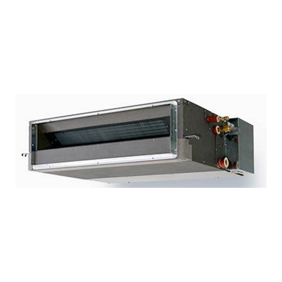
IN-THE-CEILING (DUCT) 2. Structure Name of Parts < RPI-3.0FSN2SQ - RPI-6.0FSN2SQ > Unit: mm Part Name Model RPI-3.0FSN2SQ 1,076 Fan Motor RPI-4.0FSN2SQ 1,076 Heat Exchanger RPI-5.0FSN2SQ 1,300 1,000 Distributor RPI-6.0FSN2SQ 1,300 1,000 Strainer Micro-Computer Control Expansion Valve Electrical Control Box... - Page 10 IN-THE-CEILING (DUCT) < RPI-7.0FSN2SQ > 1430 Part Name Fan Motor Heat Exchanger Distributor Micro-Computer Control Expansion Valve Strainer Electrical Control Box Refrigerant Gas Pipe Connection Refrigerant Liquid Pipe Connection Drain Pipe Connection Float Switch Drain Pan Air Outlet Air Inlet P5414985 2-12 TC-12001...
-
Page 11: Necessary Tools And Instrument List For Installation
IN-THE-CEILING (DUCT) Necessary Tools and Instrument List for Installation Tool Tool Tool Handsaw Plier Cutter for Wires Phillips Screwdriver Pipe Cutter Gas Leak Detector Vacuum Pump Brazing Kit Leveller Refrigerant Gas Hose Hexagon Wrench Clamper for Solderless Terminals Megohmmeter Spanner Hoist (for Indoor Unit) Copper Pipe Bender Weigher... - Page 12 IN-THE-CEILING (DUCT) Table 4.1 Factory-Supplied Accessories < RPI-3.0FSN2SQ - RPI-6.0FSN2SQ > Accessory Q'ty Purpose Flange For Air Outlet Flange For Air Inlet Screw For Fixing Flanges Hose Clamp For Drain Hose Connection Insulation For Refrigerant Liquid Piping (22 IDx130) Insulation...
-
Page 13: Initial Check
Fig. 4.1. facilities where there are electronic waves from medical equipment. < RPI-3.0FSN2SQ - RPI-6.0FSN2SQ > (A) Do not install the indoor unit where the electromagnetic wave is directly radiated to the electrical box, remote control cable or remote control switch. -
Page 14: Installation
(1) Apply vibration absorbing mats (10t) under the indoor unit. Separate the indoor unit in the following order. < RPI-3.0FSN2SQ - RPI-6.0FSN2SQ > (1) Remove the 4 bolts (M6) on the back of the supply air box (Fig. 4.2). Indoor Unit... -
Page 15: Mounting On Suspension Brackets (Field-Supplied)
IN-THE-CEILING (DUCT) Rejoin the return air and supply air 4.3.4 Adjusting of Unit Level compartments in the following order. (5) Carefully place the fan assembly back into taking into account the maximum foundation the original position. gradient. (6) Fix the fan assembly onto the heat exchanger compartment with 4 bolts (M6) (Fig. -
Page 16: Connecting Supply Duct
IN-THE-CEILING (DUCT) 4.3.5 Connecting Supply Duct (1) The supply duct should be connected with the indoor unit through canvas ducts, in order to avoid supply duct connection. (2) Attach the vibration proof rubber to Sling Bolt in order to avoid abnormal sound vibration. (3) Undamped natural frequency is shown in the table. -
Page 17: Refrigerant Piping Work
(3) After connecting the refrigerant piping, seal the refrigerant pipes by using the factory- (1) Position of piping connection is shown supplied insulation material as shown in Fig below. 5.4. < RPI-3.0FSN2SQ - RPI-6.0FSN2SQ > Insulation for Refrigerant Pipe Cord Clamp Refrigerant Gas Pipe (Factory-Supplied) -
Page 18: Drain Piping
IN-THE-CEILING (DUCT) Drain Piping The position of the drain piping connection is NOTE shown in Fig. 6.1. Prepare polyvinyl chloride pipe with a 32mm When the relative humidity of inlet or ambient air outer diameter. Fasten the tube to the drain hose with the drain pan beneath the indoor unit as shown in Fig. -
Page 19: Electrical Wiring
IN-THE-CEILING (DUCT) Electrical Wiring Turn OFF the main power switch to the Wrap the accessory packing around the indoor unit and the outdoor unit before wires, and plug the wiring connection hole electrical wiring work or a periodical check is with the seal material to protect the product performed. - Page 20 IN-THE-CEILING (DUCT) Electrical Box Cover Air Inlet Remove the fixing screws for Electrical box cover. Protect the earth wire to contact with the live part. Earth Terminal Remote Control Cable (Shielded Twist Pair Cable) Power Source Line to Remote Control Switch (PC-ARF) Operating Line (Shielded Twist...
- Page 21 IN-THE-CEILING (DUCT) Electrical Box Cover Air Inlet Remove the two fixing screws for electrical box cover. Protect the earth wire to contact with the live part. Earth Terminal Remote Control Cable (Shielded Twist Pair Cable) to Remote Control Switch Power Source Line Operating Line (PC-ARF) (Shielded Twist...
-
Page 22: Field Minimum Wire Sizes For Power Source
IN-THE-CEILING (DUCT) Field Minimum Wire Sizes for Power Source Do not operate the system until all the check points have been cleared. (A) Check to ensure that the electrical resistance is more than 1 megohm, by measuring the resistance between ground and the terminal of the electrical parts. If not, do not operate the system until the electrical leakage is found and repaired. -
Page 23: Setting Of Dip Switches
IN-THE-CEILING (DUCT) Setting of Dip Switches (1) Turn OFF all the power supply to the indoor (c) Unit Model Code Setting (DSW4) and the outdoor units before Dip Switch No setting is required. setting. If not, the setting is invalid. Setting the model code of the indoor unit. -
Page 24: Setting Of External Static Pressure
Do not operate the system until all the check Setting of Model Static points have been cleared. Pressure (A) Check to ensure that the electrical RPI-3.0FSN2SQ resistance is more than 1 megohm, 70Pa (Standard) RPI-4.0FSN2SQ by measuring the resistance between RPI-5.0FSN2SQ...