Table of Contents
Advertisement
Quick Links
1. Introduction
The TB6980/TB7980 digital thermostats provide proportional plus
integral individual space temperature control in zoned commercial
HVAC systems such as hydronic and pressure dependent VAV with
or without reheat. There are four different models:
• TB7980A (single output, modulating)
• TB7980B (multiple output modulating)
Depending on the models, the thermostat can have up to three out-
puts for the following applications:
Floating or Modulating damper/valve actuator control
Damper/valve actuator control with duct reheat and auxiliary
heat (B models only)
Hydronic systems (room control, perimeter heating and cool-
ing)
Accessories
R841 family of electromechanical relays
T7770A3002 remote room sensor
50014156-002 remote room sensor
32004800-001 bare thermistor
50014157-001 duct temperature sensor
2. Installation
2.1 Mounting Instructions
1.
Remove the thermostat from its base by unscrewing the cap-
tive screw and tilting the bottom of the thermostat up. The
screw cannot be completely removed.
2.
Pass the wires through the center hole of the base and secure
the base to the wall or onto an electrical box.
3.
Wire the thermostat. See section 2.2 for terminal designations
and section 3 for typical wiring diagrams.
4.
Reinstall the thermostat onto its base and secure with the cap-
tive screw.
TB6980/TB7980
• TB6980A (single output, floating)
• TB6980B (multiple output, floating)
TB6980/TB7980
Installation and User Guide
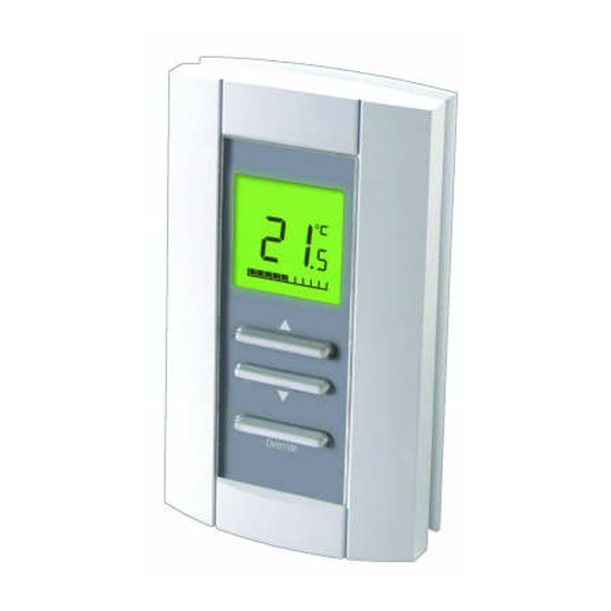
Configuration and status display
Cooling mode
Temperature
adjustment
button
Override button
2.2 Terminal Designations
The designations of the terminals vary according to the particular
model of thermostat. Refer to the following table for the description
of each terminal.
TERMINAL
DESCRIPTION
1
24 VAC
Power supply
2
COM
3
AN1
4
COM
Output 1
3
OPEN
4
CLOSED
5
T2/AN2
Output 2 (TB6980B and TB7980B models)
6
T2/COM
7
T3
Output 3 (TB6980B and TB7980B models)
8
T3
9
COM
External sensor input. (For applications requiring
10
SENSOR
an external sensor, see section 4.2.)
9
COM
Mode Changeover input (N.O. contact). See sec-
11
C-Over
tion 5.5.2.
9
COM
Night Setback activation input (N.O. contact).
12
NSB
See section 5.6.
Note: To configure the terminals, see section 4.
ZonePRO Thermostats
Heating mode
Temperature display
Output power display
TB7980 models
TB6980 models
1/6
Advertisement
Table of Contents

Related Manuals for Honeywell TB6980


Summary of Contents for Honeywell TB6980
- Page 1 TB6980/TB7980 Installation and User Guide ZonePRO Thermostats 1. Introduction The TB6980/TB7980 digital thermostats provide proportional plus integral individual space temperature control in zoned commercial Configuration and status display HVAC systems such as hydronic and pressure dependent VAV with or without reheat. There are four different models: •...
-
Page 2: Typical Applications
FIGURE 4: Temperature control of fresh air supply TB7980B TB7980B CAUTION CAUTION Do not connect Do not connect common to ground common to ground FIGURE 5: Changeover and NSB inputs sharing the same FIGURE 6: Changeover and NSB inputs using different 24-Vac 24-Vac transformer transformers TB6980/TB7980... -
Page 3: Configuration Menus
9 18°F (9°C) 8 160 (35°C) (10°C) 9 90% If Output 2 type is set to 0-4, set the SW6 switch to Triac. If the output type is set to 5-8, set the switch to Analog (see section 4.7). TB6980/TB7980... -
Page 4: Application Types
Automatic sensor. The 50014157-001 temperature sensor is used changeover 4.3.3 Opening time (TB6980 models only) for automatic changeover. See section 5.5.1. To use the outdoor air for cooling whenever possible. The damper opening time can be set between 80 and 160 seconds. -
Page 5: Dip Switches
95°F (35°C) and “minimum setpoint + 1”. The minimum setpoint can be set between 50°F (10°C) and “maximum setpoint - 1”. The thermostat can switch between heat mode and cool mode either via: • the automatic changeover • the changeover input TB6980/TB7980... -
Page 6: Technical Specifications
OVERRIDE is This warranty does not cover removal or reinstallation costs. This warranty shall not apply if it is shown by Honeywell that the defect or malfunction was displayed. caused by damage which occurred while the product was in the possession 5.7 Error Codes...
Need help?
Do you have a question about the TB6980 and is the answer not in the manual?
Questions and answers